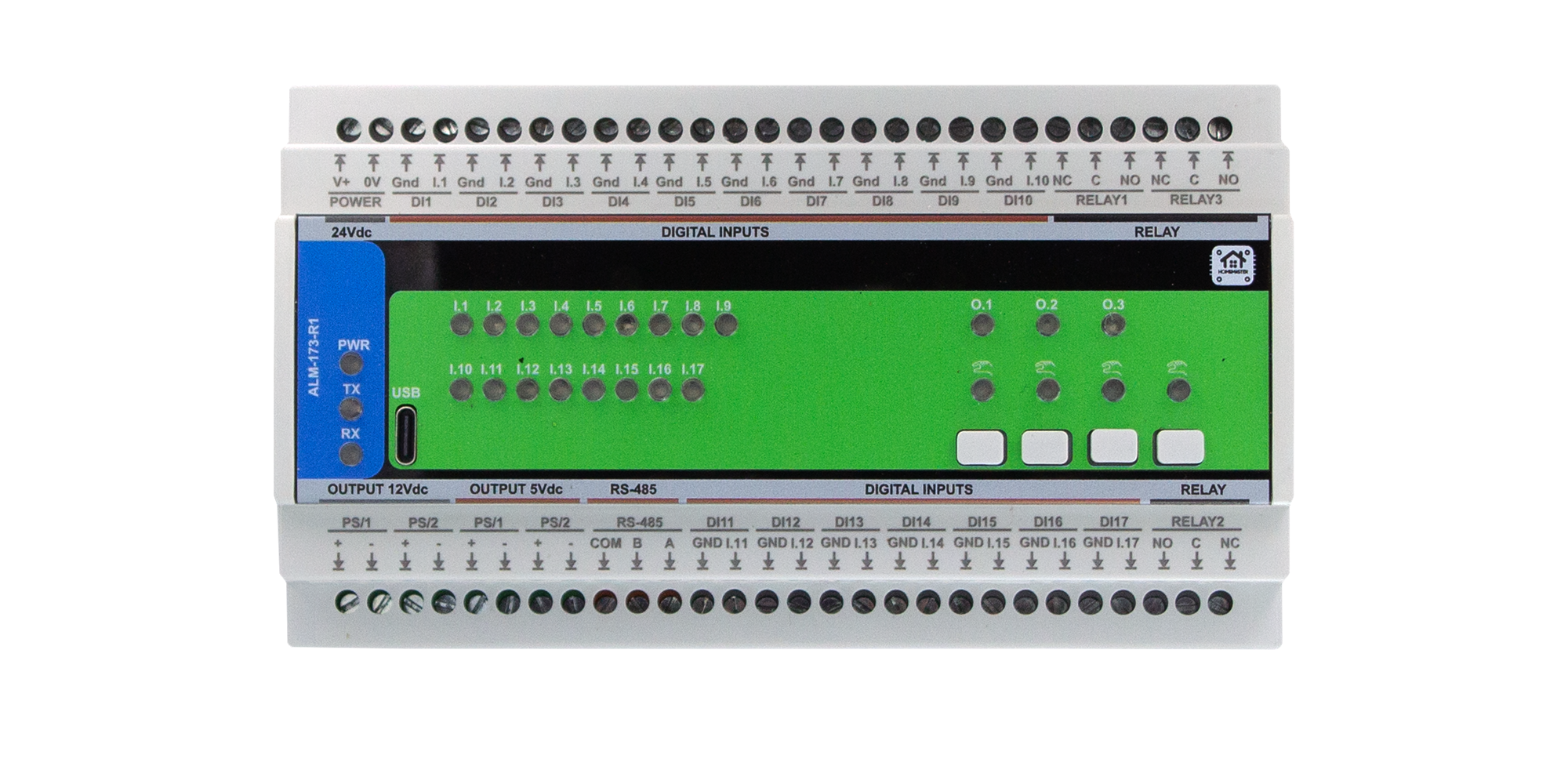
ALM-173-R1 Module Configuration
Configure Modbus settings, 17 digital inputs, 3 relays, 4 buttons, 4 LEDs and alarm modes via Web Serial.
Configure Modbus settings, 17 digital inputs, 3 relays, 4 buttons, 4 LEDs and alarm modes via Web Serial.
Configure enable, invert, and alarm group per input.
Configure enable, invert, and alarm group mapping.
Map physical buttons to acknowledge or override actions.
Configure indicator behavior for alarm and override states.