homemaster-dev
Firmware Version: 2025-07 snapshot
STR-3221-R1 — Module for Smart Lighting & I/O Control
HOMEMASTER – Modular control. Custom logic.
1. Introduction
1.1 Overview of the STR-3221-R1
The STR-3221-R1 is a compact and configurable smart LED / I/O controller designed for multi-channel LED lighting and automation control in architectural and industrial applications.
It provides 32 MOSFET-switched outputs (open-drain, low-side, 12–24 V DC) for LED loads, along with 4 opto-isolated 24 V digital inputs and 4 local buttons each with indicator LEDs.
Configuration is handled through a browser-based WebConfig interface via USB-C (Web Serial) — no additional software or drivers are required.
The module communicates with a MicroPLC/MiniPLC or any Modbus master via RS-485 (Modbus RTU), making it ideal for staircase lighting, building automation, ambient illumination, alarm signaling, or other automation systems.
Internally, it features robust isolation, surge protection, and power regulation circuits, ensuring reliable field operation and long service life.
One-line purpose: a high-density field I/O lighting node that’s easy to wire, configure, and supervise from PLC, SCADA, or home automation platforms.
1.2 Features & Architecture
| Subsystem | Qty | Description |
|---|---|---|
| Digital Inputs | 3 | Opto-isolated 3V3 DC on terminals: IN1 (GND,+), IN2 (GND,+) for motion sensors, One DI for switch |
| MOSFET Outputs | 32 | Low-side SI2307A per channel (O1…O32), 12–24 V loads; flyback SS24 diodes; grouped with shared VCC pins. |
| LED Driver ICs | 4 | TLC59208F (8-ch constant-current sinks) used for status/indication and channel grouping/PWM. |
| Buttons | 4 | SW1–SW4 for test/override or user logic. |
| Status LEDs | 4 | User-assignable (steady/blink) for power/activity/logic states. |
| Modbus RTU | Yes | RS-485 via MAX485 transceiver; activity LEDs. |
| USB-C | Yes | WebConfig over Web Serial (Chromium-based browsers); ESD-protected port. |
| Power | 24 VDC | Reverse/surge-protected input; AP64501 buck → 5 V, AMS1117-3.3 LDO → 3.3 V logic. |
| MCU | RP2350 + W25Q32 | Dual-core MCU with external QSPI flash for firmware/config. |
| Protection | TVS, PTC | Surge/ESD and resettable fuses across field & comms lines. |
Note: Two additional opto input circuits exist on the PCB design, but only IN1/IN2 are brought to terminals on this enclosure revision.
1.3 System Role & Communication
- Connection to RS-485 bus: wire controller A/B/COM to the module’s A/B/COM terminals (daisy-chain friendly, terminate the ends).
- Operating mode: Modbus RTU slave; can run simple local patterns/tests from buttons, while a PLC/SCADA/HA supervises over Modbus.
- Polling: Controller reads IN1/IN2 state and writes/reads O1…O32; optional mirrors for LEDs/buttons.
- Defaults (changeable in WebConfig):
- Address:
21 - Baud:
115200(8N1)
- Address:
2. STR-3221-R1 — Technical Specification
2.1 Diagrams & Pinouts
| Diagrams & Descriptions |
|---|
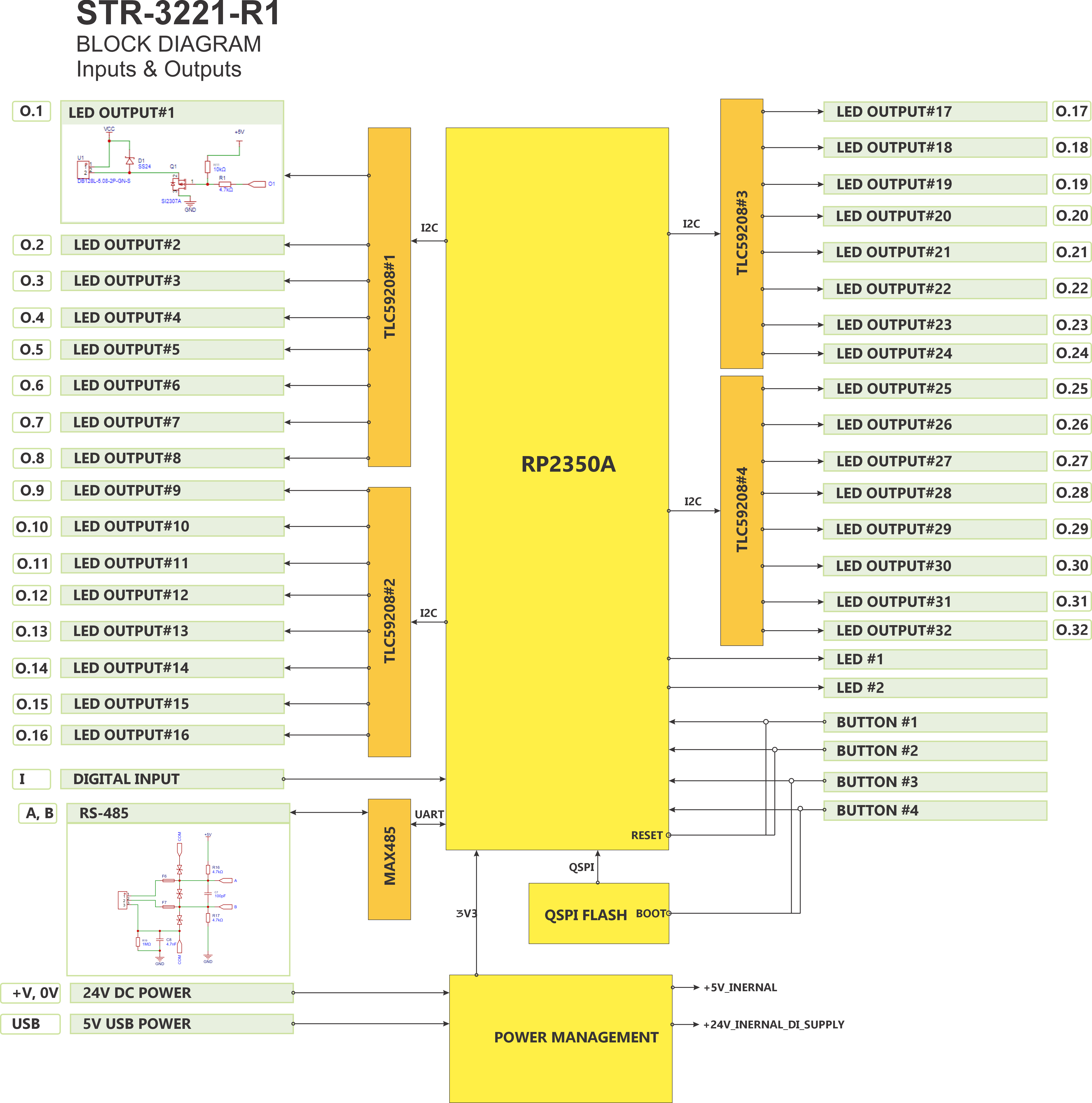 System Block Diagram — MCU, Modbus interface, power chain, and I/O groups. |
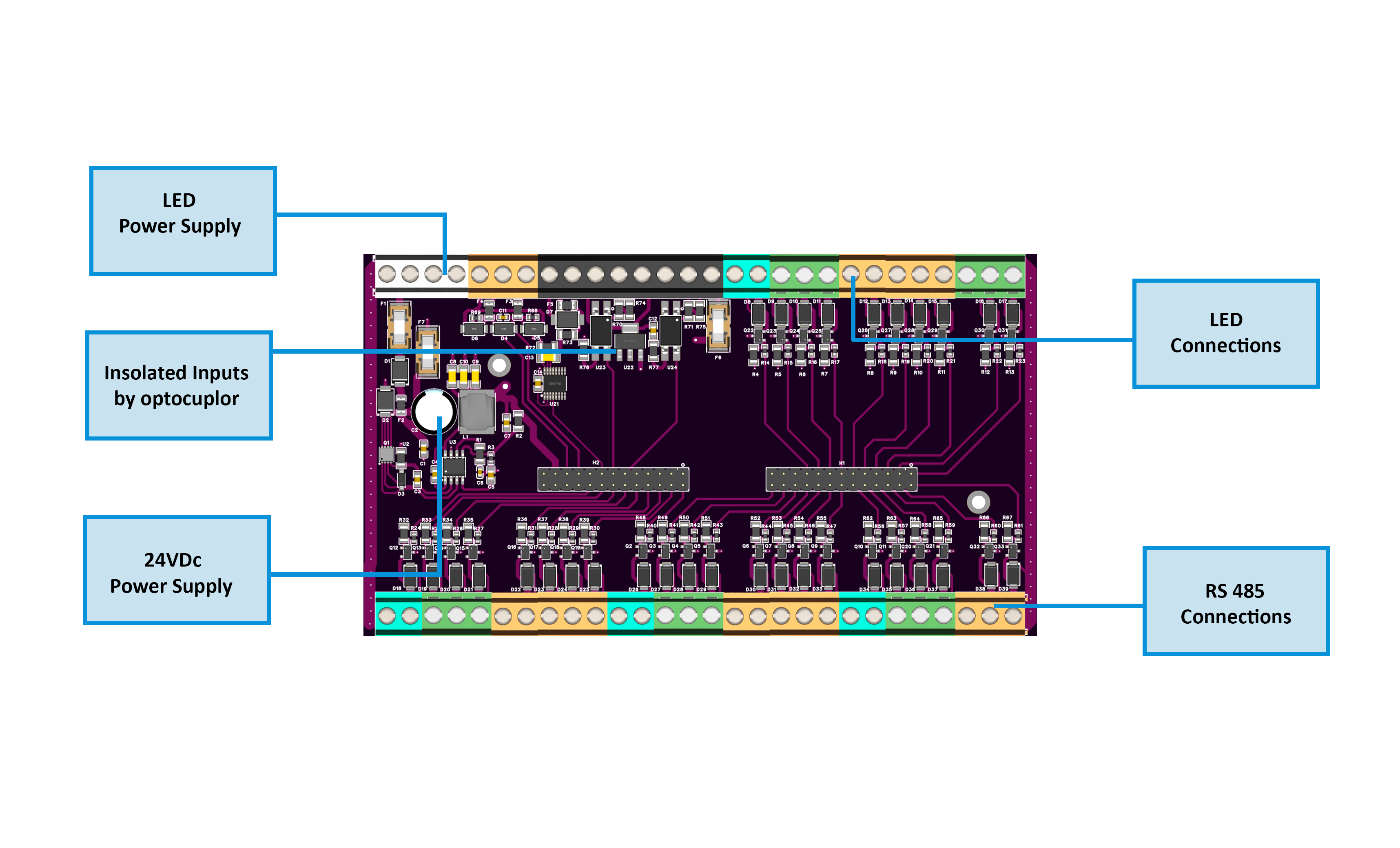 FieldBoard Layout — 32 MOSFET outputs, ISO1212 inputs, 24 VDC power rails. FieldBoard Layout — 32 MOSFET outputs, ISO1212 inputs, 24 VDC power rails. |
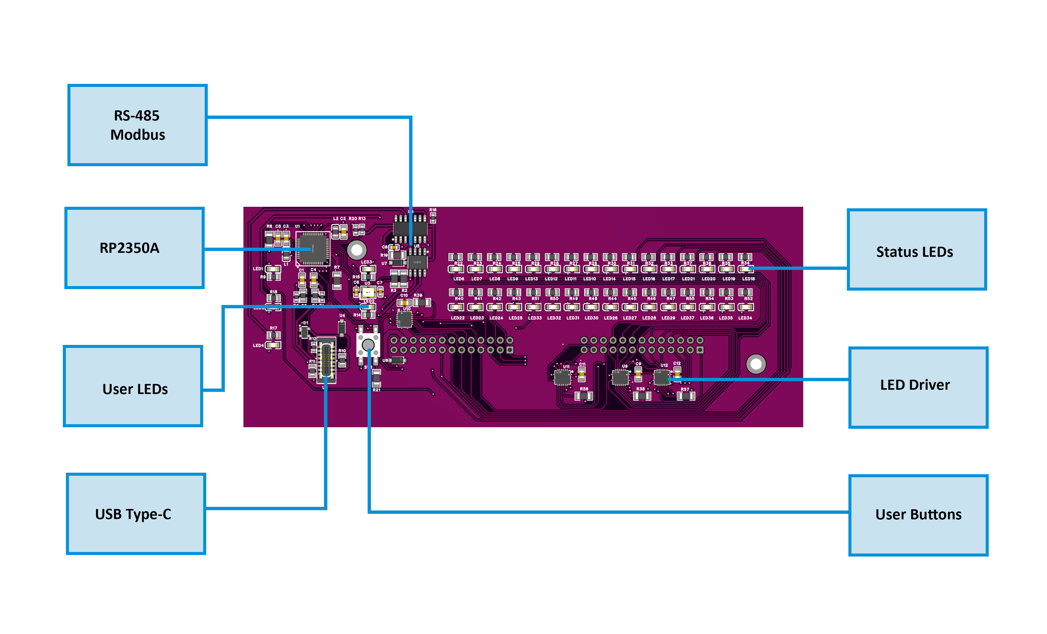 MCU Board Layout — RP2350 MCU, TLC59208F drivers, MAX485, and USB-C. MCU Board Layout — RP2350 MCU, TLC59208F drivers, MAX485, and USB-C. |
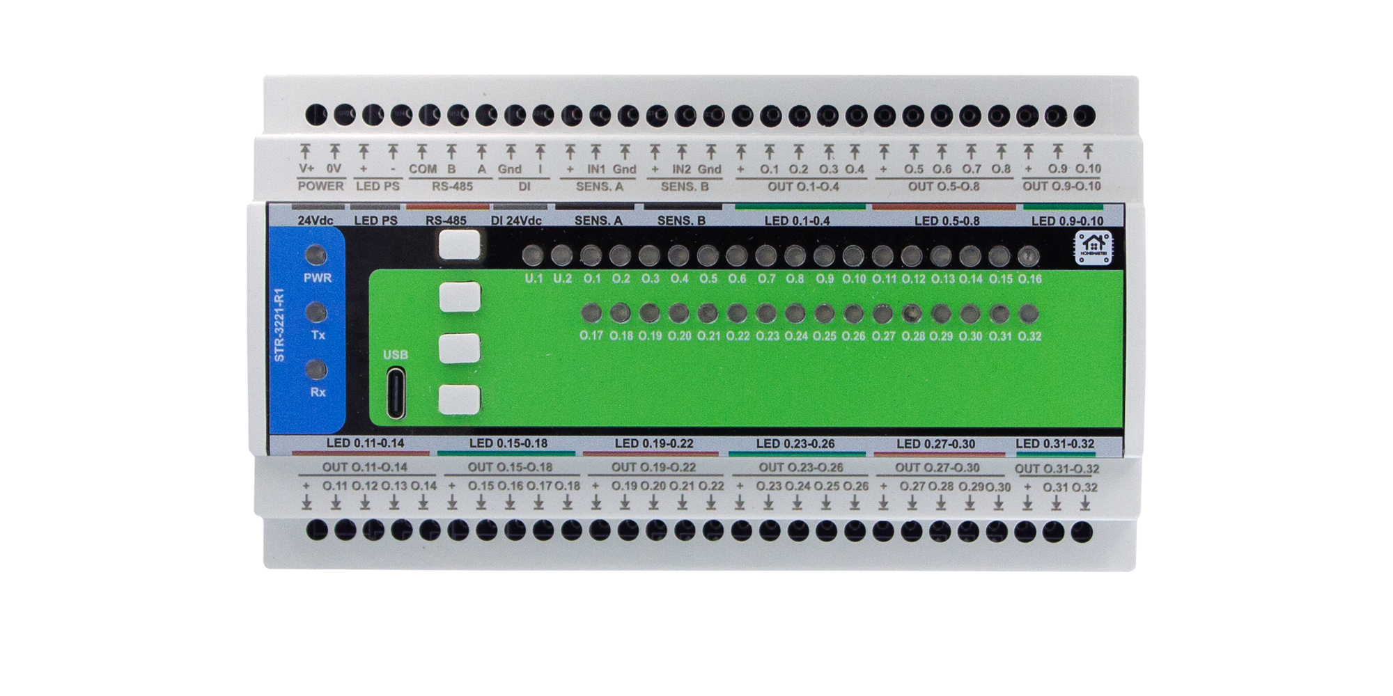
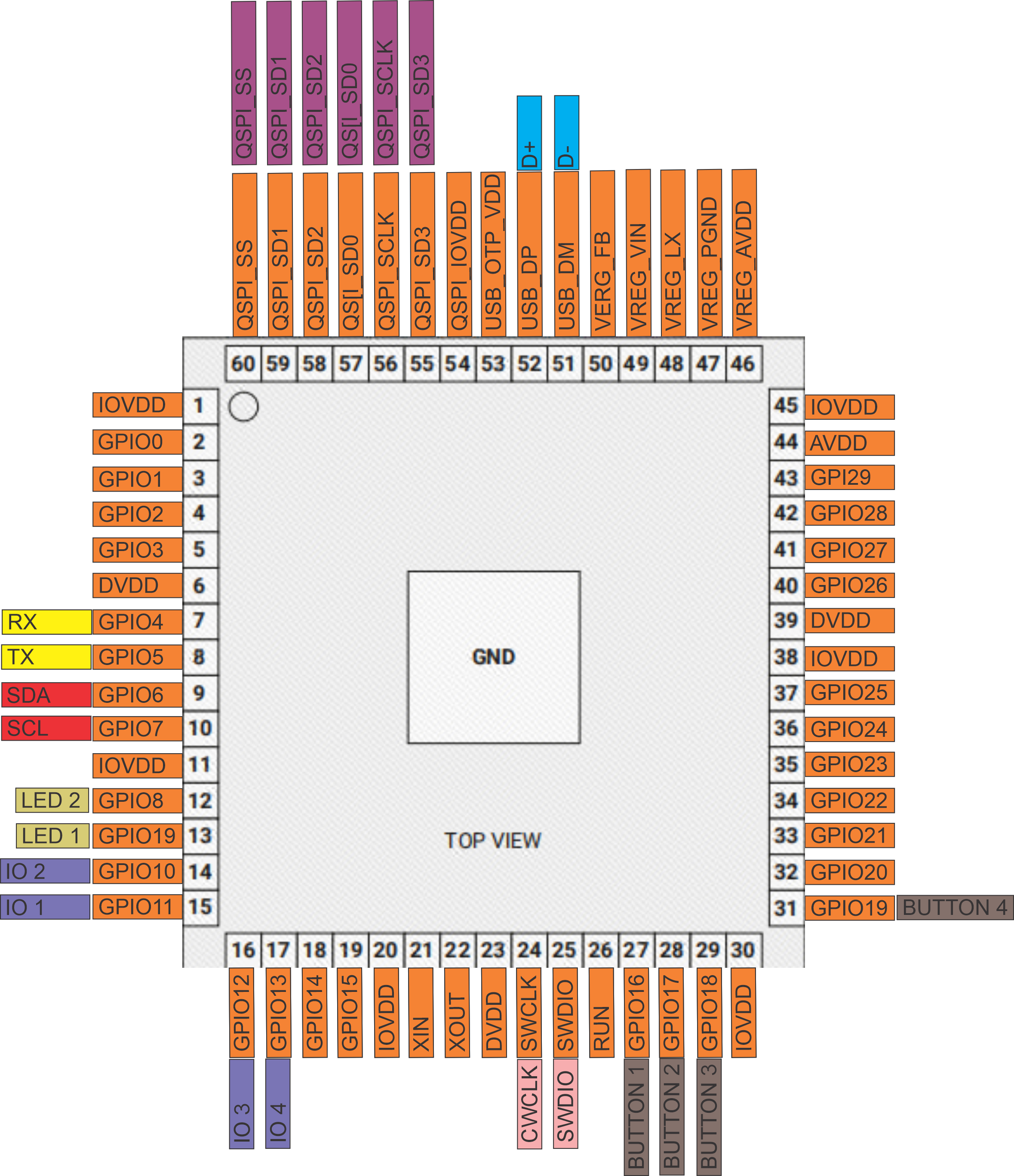 PinOut — Field wiring view with power, DI, outputs, and RS-485. PinOut — Field wiring view with power, DI, outputs, and RS-485. |
2.2 I/O Summary
| Interface | Qty | Description |
|---|---|---|
| Digital Inputs | 2 | Opto-isolated 24 VDC via ISO1212 (U23), surge-protected (F6/F7, D39). |
| Outputs | 32 | Low-side MOSFET (SI2307A) channels with SS24 flyback diodes, grouped with shared VCC rails. |
| Buttons | 4 | Local control / override / test switches. |
| Status LEDs | 4 | User-assignable (power, activity, or logic indicator). |
| RS-485 (Modbus RTU) | 1 | Communication bus; A/B/COM terminals. |
| USB-C (Setup Port) | 1 | WebConfig / firmware interface (not for powering field devices). |
| Power Input | 1 | 24 VDC (V+, 0V); reverse and surge-protected; onboard 5 V / 3.3 V regulation. |
| Sensor Rails (SENS.A / SENS.B) | 2 pairs | Fused 24 V auxiliary rails for external sensors (low current). |
2.3 Electrical Specifications
| Parameter | Min | Typ | Max | Unit | Notes |
|---|---|---|---|---|---|
| Supply Voltage (V+) | 20 | 24 | 30 | VDC | SELV input; reverse/surge protected. |
| Logic Rails | — | 5 / 3.3 | — | VDC | Generated internally (buck + LDO). |
| Quiescent Current (no load) | — | 60 | 100 | mA | Base electronics only. |
| Full-Load Current (all outputs) | — | — | 3.0 | A | At 24 VDC with max LED load. |
| Digital Input Range | 9 | 24 | 30 | VDC | ISO1212-rated 24 V input. |
| Input Threshold (ON) | — | 8 | — | VDC | Typical ISO1212 threshold. |
| Sensor Rail Output | — | 24 | — | VDC | Fused 200 mA (total SENS.A + SENS.B). |
| Output Type | — | — | — | — | Low-side MOSFET (SI2307A) 1 A max per channel. |
| Flyback Protection | — | — | — | — | SS24 diodes on each channel. |
| Communication | — | — | — | — | RS-485 (MAX485), 9600–115200 bps. |
| Isolation | — | — | — | — | Optical (ISO1212 + galvanic separation). |
| Operating Temperature | 0 | — | 40 | °C | 95 % RH non-condensing. |
⚙️ Design domains:
- Field side: 24 VDC isolated (DI, outputs).
- Logic side: 5 V / 3.3 V MCU, I²C bus, USB-C protected.
- Communication side: RS-485 isolated by line TVS + fuses.
2.4 Firmware Behavior
| Function | Description |
|---|---|
| Input Processing | Debounced and optically isolated; logic reported via Modbus coils/registers. |
| Output Control | 32 channels controlled via Modbus write commands; supports PWM dimming and timed activation sequences. |
| Button Actions | Assignable in firmware: manual test, override ON/OFF, or reset function. |
| LED Feedback | Configurable for steady, blink, or activity indication via TLC59208F drivers. |
| Override Priority | Local overrides (buttons) take precedence over Modbus commands until released. |
| WebConfig (USB-C) | Provides Modbus address setup, baud-rate selection, live I/O status, and firmware update through Web Serial. |
| Startup Logic | On power-up, outputs default to OFF until first Modbus command or internal script execution. |
| Fault Handling | Overcurrent or thermal events trigger fault LED indication; recover automatically when condition clears. |
🧩 Note:
The STR-3221-R1 shares the same firmware architecture as other HOMEMASTER I/O modules, enabling unified Modbus mapping, button/LED behavior, and WebConfig interface.
3. Use Cases
These example illustrate how the STR-3221-R1 can be integrated into real-world automation or lighting systems.
Motion-Based Stair Lighting
What it does:
Automatically lights stair LEDs in sequence when motion is detected at the top or bottom of the staircase.
Setup:
- Connect motion sensors to IN1 (bottom) and IN2 (top) terminals.
- Connect each stair LED segment to outputs O1–O32 (low-side switching).
- Set WebConfig → STR-3221-R1 .
- Program MicoPLC/MiniPLC to poll IN1/IN2 and activate LEDs in a timed sequence.
- Use Button 1 as “Manual Test / All ON” and Button 2 as “All OFF”.
4. Safety Information
The STR-3221-R1 is a SELV (Safety Extra-Low Voltage) device.
Improper wiring, power application, or grounding may cause malfunction or damage.
Follow all safety and wiring practices described below.
4.1 General Requirements
| Requirement | Detail |
|---|---|
| Qualified Personnel | Only trained technicians familiar with control panels, PLCs, and SELV wiring should install or service this module. |
| Power Isolation | Always disconnect 24 VDC power and RS-485 trunk before touching or rewiring terminals. |
| Rated Voltages Only | Use SELV 24 VDC power supplies; never connect AC mains or high-voltage lines. |
| Grounding | Properly bond the panel’s protective earth (PE) to reduce EMI and static discharge. |
| Enclosure | Mount in a clean, dry, ventilated enclosure; avoid moisture, conductive dust, or vibration. |
| Static Protection | Handle circuit boards only with ESD precautions (grounded strap and antistatic mat). |
4.2 Installation Practices
-
DIN Mounting:
Mount securely on 35 mm DIN rail (EN 50022) using the rear clip. Apply strain relief on all connected cables to prevent terminal stress. - Isolation Domains:
The module contains isolated sections:- Field Power (24 VDC_FUSED) for outputs and inputs
- Logic Power (5 V / 3.3 V) for MCU
Never short or bridge GND_FUSED (field ground) with logic ground unless specifically required by system design.
-
Sensor Power Connection:
Connect sensors or switches only to DI terminals rated for 24 VDC inputs.
Sensor rails labeled SENS.A / SENS.B provide limited, fused 24 V service for low-power sensors — do not backfeed or parallel with other supplies. -
Wiring Discipline:
Use ferruled, properly sized conductors (0.25–1.5 mm²).
Route communication (RS-485) and power lines separately to reduce noise coupling. - Testing Before Power-Up:
Verify all terminal polarities, check RS-485 A/B orientation, and confirm no shorts between supply rails.
4.3 Interface Warnings
⚡ Power (24 VDC Input / LED Supply)
| Area | Warning |
|---|---|
| 24 VDC Power (V+ / 0V) | Use only clean, regulated SELV 24 VDC. Reverse polarity is protected but repeated mistakes may damage fuses. |
| LED PS (+/–) | Provides the external LED load voltage (typically 12–24 VDC). Do not short or exceed rated current capacity of field wiring. |
| Sensor Rails (SENS.A / SENS.B) | For powering external sensors only; limited current via fuses. Never use to drive loads or feed back external power sources. |
🔌 Digital Inputs (DI)
| Area | Warning |
|---|---|
| Input Type | Accepts 24 VDC logic signals (PNP, dry contact). No AC or high-voltage inputs. |
| Isolation | Each input isolated through ISO1212; do not bridge input commons to other supplies. |
| Debounce | Hardware filtering provided; avoid additional large RC filters that delay detection. |
| Protection | Each input fused and surge-protected (F6/F7, D39). Replace fuses only with identical PTC parts. |
⚙️ Outputs (O1…O32)
| Area | Warning |
|---|---|
| Output Type | Low-side MOSFET (SI2307A) sinks; maximum load per channel 1 A (12–24 VDC). |
| Polarity | Connect load +V to VCC group rail, load – to output terminal (O#). |
| Flyback / Inductive Loads | Built-in SS24 diodes; for large inductive loads add external RC or TVS snubbers. |
| Shared Rail | Each 8-channel group shares a VCC rail — ensure consistent LED supply voltage. |
🔄 RS-485 (Modbus RTU)
| Area | Warning |
|---|---|
| Wiring | Use twisted pair (shielded) cable for A/B lines. Maintain consistent polarity along the trunk. |
| Termination | Terminate with 120 Ω resistors at both physical ends only. |
| Ground Reference | Connect COM to controller’s reference if using separate power supplies. |
| Topology | Daisy-chain preferred. Avoid star connections to prevent reflections. |
| Surge Protection | Integrated TVS diodes and fuses protect the transceiver; still use proper cable shielding in industrial environments. |
🧠 USB-C (Service / WebConfig)
| Area | Warning |
|---|---|
| Purpose | For setup, diagnostics, and firmware only. Not for powering sensors or external devices. |
| Connection | Connect to PC via isolated USB hub if the RS-485 bus is long or exposed. |
| During Operation | Disconnect USB-C when running in the field; avoid ground loops with PLC systems. |
| ESD | Port is ESD-protected, but avoid static discharge when plugging in cables. |
⚠️ Summary:
The STR-3221-R1 is designed for SELV 24 VDC systems. Never connect mains voltages.
Always de-energize and confirm wiring before service. Proper isolation, grounding, and shielding ensure safe and reliable operation.
5. Installation & Quick Start
5.1 What You Need
| Item | Description |
|---|---|
| Module | MODULE-CODE unit |
| Controller | MiniPLC/MicroPLC or Modbus RTU master |
| PSU | Regulated 24 VDC |
| Cable | USB-C and RS-485 twisted pair |
| Software | Browser with Web Serial support |
5.2 Power
- Describe 24 VDC input
- List expected current
- Explain isolated sensor power if present
5.3 Communication
- RS-485 pinout
- Address & baudrate setup
- Use of COM/GND reference
5.4 Installation & Wiring
Use diagrams and explain:
- Inputs
- Relays
- Sensor rails (12/5V)
- RS-485 terminals
- USB port
5.5 Software & UI Configuration
Cover:
- WebConfig setup (address, baud)
- Input enable/invert/group
- Relay logic mode (group/manual)
- LED and Button mapping
5.6 Getting Started
Summarize steps in 3 phases:
- Wiring
- Configuration
- Integration
6. Modbus RTU Communication
Include:
- Address range and map
- Input/holding register layout
- Coil/discrete inputs
- Register use examples
- Polling recommendations
7. ESPHome Integration Guide
Only if supported. Cover:
- YAML setup (
uart,modbus,package) - Entity list (inputs, relays, buttons, LEDs)
- Acknowledge, override controls
- Home Assistant integration tips
8. Programming & Customization
8.1 Supported Languages
- MicroPython
- C / C++
- Arduino IDE
- PlatformIO
The STR-3221-R1 firmware is compatible with standard RP2350 toolchains and examples.
It uses Modbus RTU libraries, Web Serial (for configuration), and I²C for LED drivers (TLC59208F).
8.2 Flashing via USB-C
Firmware updates and development are performed over the USB-C service port.
The module enumerates as a USB Serial device when connected to a PC.
Steps:
- Connect the module to your PC via USB-C.
- Hold Buttons 1 + 2 → the module enters BOOT mode.
(USB re-enumerates as a flashing device.) - Use the Arduino IDE, PlatformIO, or the provided update utility to upload firmware.
- When flashing completes, press Buttons 3 + 4 → triggers hardware RESET and runs the new firmware.
- The module reboots and appears as a standard Modbus slave or WebConfig device.
📷 Button Combination Reference
| Function | Combination | Behavior |
|---|---|---|
| BOOT Mode | Buttons 1 + 2 | Forces the module into flash/bootloader mode |
| Hardware Reset | Buttons 3 + 4 | Restarts the MCU without clearing configuration |
| Normal Operation | — | Module runs stored firmware automatically |
8.3 Arduino / PlatformIO Notes
🧩 Required Libraries
For Arduino or PlatformIO environments, include:
#include <Arduino.h>
#include <ModbusSerial.h>
#include <SimpleWebSerial.h>
#include <Arduino_JSON.h>
#include <LittleFS.h>
#include <Wire.h>
#include <utility>
#include "hardware/watchdog.h"
⚙️ Board Configuration
| Parameter | Setting |
|---|---|
| Board | Generic RP2350 |
| Flash Size | 2 MB (Sketch 1 MB / FS 1 MB) |
| Upload Port | USB-C |
| Baud Rate | 115200 |
| Libraries | Modbus RTU, SimpleWebSerial, JSON, LittleFS, Wire |
📡 Pin Mapping Summary
| Peripheral | MCU Pin | Description |
|---|---|---|
| RS-485 TX | GPIO8 | MAX485 DI |
| RS-485 RX | GPIO9 | MAX485 RO |
| RS-485 DE/RE | GPIO10 | MAX485 Driver Enable |
| Button 1–4 | GPIO2, GPIO3, GPIO4, GPIO5 | Local input buttons |
| LED 1–4 | I²C via TLC59208F | Status indicators |
| I²C SCL / SDA | GPIO22 / GPIO23 | TLC59208F LED drivers |
| Digital Inputs (DI1/DI2) | GPIO14 / GPIO15 | From ISO1212 isolator outputs |
| QSPI Flash | GPIO55–60 | W25Q32 32 Mbit flash memory |
| USB D± | GPIO51 / GPIO52 | USB-C data lines |
8.4 Firmware Updates
🧠 How to Update
- Connect via USB-C to a PC.
- Press Buttons 1 + 2 to enter BOOT mode.
- Upload new firmware (e.g.,
default_str_3221_r1.bin) using:- Arduino IDE → “Upload”
- PlatformIO →
Upload and Monitor
- After flashing, press Buttons 3 + 4 for a safe hardware reset.
🔒 Preserving Configuration
All configuration parameters (address, baud, LED/button mappings, etc.) are stored in the MCU’s non-volatile flash and remain intact unless manually erased via WebConfig or serial command.
🩹 Recovery Methods
If flashing fails or the module is unresponsive:
- Disconnect USB-C, wait 10 seconds, and reconnect while holding Buttons 1 + 2 (force BOOT mode).
- Reflash firmware again.
- If configuration corruption occurs, select “Factory Reset” in WebConfig.
9. Maintenance & Troubleshooting
| Indicator / Action | Meaning / Resolution |
|---|---|
| PWR LED – steady ON | Module powered and running normally. |
| TX/RX LEDs – blink | Active Modbus communication on RS-485. |
| No TX/RX blink | Check A/B polarity, COM reference, and termination resistors. |
| Buttons unresponsive | Verify 3.3 V logic; reboot using Buttons 3 + 4. |
| No communication via USB-C | Ensure Chromium-based browser; close other serial apps. |
| Outputs not responding | Check 24 V LED PS supply and output VCC rail. |
| Digital inputs not changing | Verify sensor wiring polarity (INx GND/+); ensure 24 V signal present. |
| WebConfig not connecting | Use Chrome/Edge; allow serial access permission; reset module if busy. |
| Reset Device | Press Buttons 3 + 4 for a hardware reboot. |
| Full Factory Reset | Hold all Buttons 1–4 on power-up to clear configuration. |
10. Open Source & Licensing
Licensing
This project uses a hybrid licensing model.
Hardware
Hardware designs (schematics, PCB layouts, BOMs) are licensed under: CERN-OHL-W v2
Firmware & ESPHome Integration
All firmware, ESPHome configurations, and software components are licensed under: MIT License
This ensures full compatibility with ESPHome and Home Assistant while protecting hardware designs.
See LICENSE files in each directory for full terms.
11. Downloads
| Resource | Description |
|---|---|
| 🧠 Firmware (Arduino/PlatformIO) | Firmware/default_str_3221_r1/ — main sketch for Modbus, lighting, and WebConfig. |
| 🛠 WebConfig Tool | Firmware/ConfigToolPage.html — browser-based USB-C setup utility. |
| 📷 Images & Diagrams | Images/ — module photos, terminal maps, and block diagrams. |
| 📐 Schematics (PDF) | Schematics/ — FieldBoard and MCUBoard schematics for hardware developers. |
| 📄 Datasheet & Manual | Manuals/ — module datasheet and installation guide. |
| 📦 Pre-built Firmware | Releases page — compiled .bin files for direct flashing. |
12. Support
If you need help using or configuring the STR-3221-R1, visit:
- 🌐 Official Support Portal – knowledge base, ticketing, and FAQs.
- 🧰 WebConfig Tool – in-browser setup and diagnostics.
- ▶️ YouTube Channel – setup videos and feature walkthroughs.
- 💡 Hackster.io – integration examples and community projects.
- 💬 Reddit – discussion and troubleshooting community.
- 📸 Instagram – updates, showcases, and announcements.
HOMEMASTER – Modular control. Custom logic.