homemaster-dev
🚧 Project Status: Under Active Development & Testing
Important Notice: This documentation, hardware designs, and firmware are for the pre-release version of the HomeMaster system. All information is preliminary and may contain errors or be subject to change.
- Hardware: Modules are currently in the prototyping and testing phase. Final production versions may differ.
- Firmware: Firmware is under active development and is considered beta. Features, configurations, and stability are being refined.
Please use this information for evaluation and development purposes only Firmware Version: 2025-10 snapshot
WLD-521-R1 — Water Meter & Leak Detection Module
HOMEMASTER – Modular control. Custom logic.
Module Description
The WLD-521-R1 is a configurable smart I/O module designed for leak detection, water flow metering, heat energy monitoring, and local irrigation control.
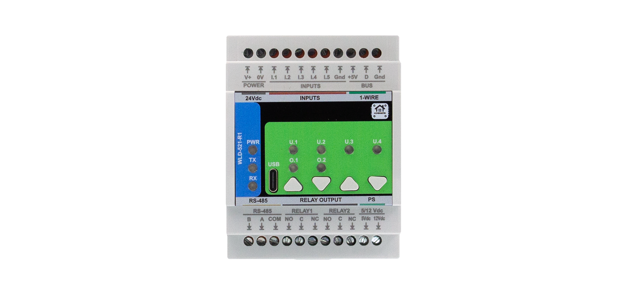
It includes 5 opto-isolated digital inputs, 2 SPDT relays, and optional 4 buttons and 4 LEDs for manual control and local status indication. Configuration is performed via the WebConfig interface over USB-C (Web Serial).
The module connects over RS-485 (Modbus RTU) to a MicroPLC or MiniPLC, enabling deployment in water management, hydronic heating, garden irrigation, and safety automation systems.
Table of Contents
- 1. Introduction
- 2. Use Cases
- 3. Safety Information
- 4. Installation & Quick Start
- 5. MODULE-CODE — Technical Specification
- 6. Modbus RTU Communication
- 7. ESPHome Integration Guide (if applicable)
- 8. Programming & Customization
- 9. Maintenance & Troubleshooting
- 10. Open Source & Licensing
- 11. Downloads
- 12. Support
1. Introduction
1.1 Overview of the WLD-521-R1
The WLD-521-R1 is a DIN‑rail smart I/O module for leak detection, pulse water metering, ΔT heat monitoring, and local irrigation control. It exposes 5 opto‑isolated digital inputs, 2 SPDT relays, 4 user buttons, and 4 status LEDs and is serviced over USB‑C.
It integrates with a MiniPLC/MicroPLC (or other PLC/SCADA/HA controllers) via Modbus RTU over RS‑485. Configuration is done in a browser using the WebConfig tool (Web Serial over USB‑C): set Modbus params, choose per‑input modes (sensor/counter), link 1‑Wire temperature sensors, and enable autonomous irrigation/flow‑safety logic.
In one line: a resilient water‑safety/flow module with local logic that still plays perfectly with your PLC and Home Assistant stack.
1.2 Features & Architecture
| Subsystem | Qty | Description |
|---|---|---|
| Digital Inputs | 5 | Opto‑isolated inputs with MOSFET front‑ends, debouncing, and isolated return (GND_ISO); suitable for dry contacts or pulse flowmeters. |
| Analog Outputs | 0 | — |
| Relays | 2 | SPDT dry contacts (~3 A @ 250 VAC); driven via opto‑isolated stages and RC/snubber-protected. Terminals NO/COM/NC exposed. |
| 1‑Wire Bus | 1 | Protected 3‑pin header (+5 V / DATA / GND) with level shifting and ESD protection; supports DS18B20 sensors. |
| LEDs | 4 user + status | 4 user LEDs controlled via transistor drivers; additional LEDs for power and RS‑485 TX/RX activity. |
| Buttons | 4 | Front-panel tactile buttons connected to MCU GPIOs for relay override, irrigation control, and test functions. |
| Modbus RTU | Yes | RS‑485 transceiver with surge/bias/ESD protection and DE/RE control. Typical config: 19200 baud, 8N1. |
| USB‑C | Yes | Type-C port with ESD protection and Web Serial interface; used for configuration via WebConfig. |
| Power | 24 VDC | Fused, reverse-protected input. Internal buck regulator provides +5 V and +3.3 V. Isolated +5 V and +12 V rails available for sensor power. |
| MCU | RP2350A | Dual-core MCU with QSPI flash and 12 MHz crystal; SWD debug header available. |
| Protection | TVS, PTC, ESD | Multi-stage protection on RS‑485 and USB lines; isolated sensor rails; opto-isolated inputs; snubbers on relays. |
Optional: 1‑Wire bus for DS18B20 sensors (e.g. supply/return temperatures for heat energy monitoring).
1.3 System Role & Communication 💧
The WLD-521-R1 is a smart Modbus RTU slave. It can operate autonomously for leak/flow/irrigation safety logic, while exposing its I/O and sensors to a PLC, ESPHome controller, or SCADA system.
| Role | Description |
|---|---|
| System Position | Expansion module on RS-485 trunk |
| Master Controller | MiniPLC / MicroPLC or any third-party Modbus RTU master |
| Address / Baud | Configurable via WebConfig (1–255, 9600–115200 baud) |
| Bus Type | RS‑485 multi-drop (A/B/COM terminals) |
| USB‑C Port | For configuration/diagnostics using Web Serial (Chrome/Edge) |
| Default Modbus ID | 3 (user-changeable per module) |
| Daisy-Chaining | Multiple modules supported; assign unique IDs to each device |
⚠️ Note: If multiple WLD modules are connected to the same RS‑485 segment, make sure to assign unique Modbus addresses using WebConfig.
2. Use Cases
The WLD-521-R1 supports a range of real-world applications in leak detection, flow metering, hydronic energy monitoring, and irrigation control. Below are practical scenarios with step-by-step configuration.
💧 1) Basement Leak Alarm + Auto Shut-off
Goal: Detect water leaks and immediately shut off the water supply using a relay-controlled valve.
Steps:
- Set DI1 as Water sensor
- Enable DI1 and set Action = Toggle
- Set Control target = Relay 1
- Wire a motorized shut-off valve (normally open) to R1
- (Optional) Assign LED1 to blink on DI1 or R1
🌿 2) Garden Irrigation with Flow Supervision
Goal: Automate watering safely with flow monitoring and environmental interlocks.
Steps:
- Go to Irrigation → Zone 1
- Set Valve relay = Relay 2, Flow DI = DI2
- Enable Use flow supervision
- Configure:
- Min rate = 0.2 L/min
- Grace = 8 s
- Timeout = 1200 s
- Target liters = 50
- Add interlocks:
- DI_moist = DI3 (dry = run)
- DI_rain = DI4 (rain = block)
- R_pump = Relay 1 (pump ON when watering)
- Enable Window: 06:00–08:00 with Auto-start
📈 3) Water Consumption Metering (Billing)
Goal: Track water usage in liters using pulse flow meters.
Steps:
- Set DI2 to Water counter
- Enter Pulses per liter = 450 (typical)
- Adjust Rate × / Total × as needed for calibration
- Use Reset total to baseline reading
- Use Calc from external after external validation
- View Live rate (L/min) and Total (L) in WebConfig
🔥 4) Heat Energy Monitoring (Hydronic ΔT Loops)
Goal: Measure heat power and energy from flow and temperature sensors.
Steps:
- Set DI3 = Water counter
- Enable Heat on DI3
- Assign Sensor A = #1 (supply), Sensor B = #2 (return)
- Set thermal constants:
- cp = 4186 J/kg·°C
- ρ = 1.0 kg/L
- Adjust Calibration × if needed
- View TA, TB, ΔT, Power (W), Energy (J/kWh)
- Use Reset energy to zero counters
3. Safety Information
These safety instructions apply to the WLD‑521‑R1 module. Improper handling or wiring can cause equipment damage, system failure, or personal injury.
⚠️ SELV only — This device operates on Safety Extra Low Voltage (24 VDC only). Never apply AC mains or high-voltage sources.
3.1 General Requirements
| Requirement | Detail |
|---|---|
| Qualified Personnel | Only trained installers or technicians may handle wiring and system integration. |
| Power Isolation | Disconnect 24 VDC power before modifying terminals or servicing the device. |
| Environmental Limits | Install inside a dry, clean DIN enclosure. Avoid condensation, dust, or vibration. |
| Grounding | Connect 0 V, RS-485 COM, and GND_ISO appropriately. Maintain logic and sensor isolation. |
| Voltage Compliance | Observe electrical ratings: 24 VDC supply, 5/12 V sensor outputs, max 3 A relay load. |
3.2 Installation Practices
| Task | Guidance |
|---|---|
| DIN Mounting | Secure module on 35 mm DIN rail. Apply strain relief to all wiring. |
| ESD Precaution | Use anti-static strap and handle boards by casing only. |
| Power Wiring | Connect regulated 24 VDC to V+ / 0V terminals. Fuse upstream. |
| Relay Wiring | Use NO / COM / NC terminals for each relay. Relays are dry contact SPDT only. External loads must have their own power. |
| Digital Inputs | Connect dry-contact sensors or open-collector devices to I1–I5, with return to GND_ISO (not 0V). |
| Sensor Power | Use +5 V or +12 V outputs (right-side terminals) for low-power field sensors only. |
| GND Domains | Keep GND_ISO (inputs) and 0 V / GND (logic) isolated unless explicitly bridged. |
| RS-485 Wiring | Wire A/B/COM to RS‑485 master. Maintain A↔A, B↔B polarity. COM = signal reference. Terminate both ends with ~120 Ω. |
| Commissioning | Before applying power: verify polarity, relay contact wiring, RS‑485 line, and ensure sensor loads are within spec. |
3.3 I/O & Interface Warnings
🔌 Power
| Interface | Warning |
|---|---|
| V+ / 0V (Top-left) | Connect only regulated 24 VDC. Reverse protected. Never exceed 30 V. |
| +5 V / +12 V (Bottom-right) | Isolated sensor supply. Use for dry-contact sensors only. Protected by DC-DC and fuses. Not for powering relays or actuators. |
⏸ Inputs & Relays
| Interface | Warning |
|---|---|
| Inputs I1–I5 (Top row) | Opto-isolated channels. Connect only dry-contact or open-collector sources. Return via GND (top right) (this is GND_ISO, not logic ground). |
| Relays (Bottom row) | NC / COM / NO per relay. Dry contact only. Max: 3 A @ 250 VAC / 30 VDC. Use snubbers for inductive loads (e.g. pumps, valves). |
| Relay Power | Relay contacts are not powered. External load must have its own power source. |
🔗 Communication & USB
| Interface | Warning |
|---|---|
| RS‑485 A/B/COM (Bottom left) | Use twisted pair for A/B. COM is signal ground. Protect against surges. Not suitable for long unshielded runs or outdoor wiring. |
| USB‑C (Front panel) | For setup only using Web Serial in Chrome/Edge. ESD protected. Not for field use or runtime connection. Disconnect after configuration. |
🔘 User Interface
| Element | Notes |
|---|---|
| Buttons (U1–U4) | Configurable: relay override, irrigation start/stop. Button press may override Modbus or automation logic. |
| LEDs (U1–U4) | Configurable for DI, Relay, or Irrigation indication. Driven from MCU via transistors. |
🛡 Shielding & EMC
| Area | Recommendation |
|---|---|
| Cable Shielding | Use shielded cable for RS‑485 and sensor lines. Terminate shield at controller end only. Avoid routing near motors/VFDs. |
| Inductive Loads | Use RC snubbers or TVS across relay contacts for solenoids, pumps, or coils. |
4. Installation & Quick Start
4.1 What You Need
| Category | Item | Details |
|---|---|---|
| Hardware | WLD‑521‑R1 | DIN‑rail module with 5 opto DIs, 2 SPDT relays, 4 buttons, 4 LEDs, RS‑485, USB‑C, 1‑Wire, and isolated +5 V / +12 V sensor rails. |
| Controller (master) | HomeMaster MiniPLC/MicroPLC or any Modbus RTU master device. | |
| 24 VDC PSU (SELV) | Regulated 24 VDC supply to V+ / 0V; size to include module + sensors. | |
| RS‑485 cable | Shielded twisted pair for A/B + COM (GND); use 120 Ω termination at both bus ends. | |
| USB‑C cable | Used for setup/config via WebConfig in Chromium browser. | |
| DIN enclosure | Dry, clean cabinet with DIN rail; provide strain relief and shield grounding. | |
| Software | WebConfig (browser) | Configure Address / Baud, assign Inputs / Relays / Buttons / LEDs, irrigation zones, sensors, etc. |
| ESPHome (optional) | On controller: polls Modbus, exposes WLD sensors and relays to Home Assistant. | |
| Field I/O | Dry contacts | Inputs DI1…DI5 return to GND_ISO; supports leak probes, flow meters, or buttons. |
| Relay loads | RLY1/RLY2: COM/NO/NC dry contacts; up to 3 A @ 250 VAC. Use RC/TVS snubbers for inductive loads. | |
| Sensor power (isolated) | Bottom-right +12 V / +5 V ISO terminals for low-power sensors only. Not for actuators. | |
| Tools | Screwdrivers, ferrules, meter | Verify terminal torque, polarity, and RS‑485 A/B wiring. Use 120 Ω resistors and surge protectors if needed. |
Status LEDs:
• PWR – steady ON when powered
• TX/RX – blink on RS‑485 activity
• USB – active when connected for WebConfig
4.2 Power
The WLD‑521‑R1 operates from a regulated 24 VDC supply connected to the top terminals labeled V+ and 0V. The power supply should be SELV-rated and appropriately sized.
Power Supply Notes
- Input: 24 VDC, reverse-protected and fused onboard
- Internal regulation:
- 5 V logic (buck regulated via AP64501)
- 3.3 V logic (via AMS1117-3.3)
- +12 V ISO (for field sensors via B2412S‑2WR3)
- +5 V ISO (via B2405S‑2WR3)
Power Budget (Estimates)
| Load | Typical Current |
|---|---|
| Base logic + LEDs | ~50 mA |
| Each relay (coil) | ~40–60 mA |
| Sensor rails (total) | ≤150 mA (shared between +5 V ISO / +12 V ISO) |
Recommended PSU: ≥300 mA per module (with 30% headroom).
⚠️ Only use the sensor rails for low-power sensors like leak probes and flow meters.
Never power relays, valves, or actuators from the module’s +5 V / +12 V outputs.
4.3 Communication
The WLD‑521‑R1 uses Modbus RTU over RS‑485 for all runtime communication, and USB‑C for setup via browser.
RS‑485 Pinout (Bottom Left Terminals)
| Terminal | Function |
|---|---|
| A | RS‑485 A (Data +) |
| B | RS‑485 B (Data –) |
| COM | RS‑485 reference ground (connect to controller GND) |
- Wire A → A, B → B, COM → COM
- Use twisted-pair cable and terminate at both ends (120 Ω)
- Avoid star topologies; keep stubs short
- Shielded cable is recommended for EMI immunity
Modbus Settings
| Parameter | Default | Range |
|---|---|---|
| Address | 3 | 1–255 (set via WebConfig) |
| Baudrate | 19200 | 9600–115200 (WebConfig) |
| Format | 8N1 | 8 data bits, no parity, 1 stop bit |
WebConfig allows you to set the Modbus address and baudrate via USB‑C before connecting to a PLC or ESPHome controller.
WLD-521-R1 Modbus Register Table
Function Codes
- FC02 - Read Input Status (Discrete Inputs)
- FC03 - Read Holding Registers
- FC05 - Write Single Coil
- FC01 - Read Coils
Input Status (FC02) - Read Only
| Address | Name | Type | Description |
|---|---|---|---|
| 1-5 | DI1-DI5 | Boolean | Digital Input states (0=OFF, 1=ON) |
| 60-61 | RLY1-RLY2 | Boolean | Relay output states (0=OFF, 1=ON) |
| 90-93 | LED1-LED4 | Boolean | User LED states (0=OFF, 1=ON) |
| 100-103 | BTN1-BTN4 | Boolean | Button pressed states (0=Released, 1=Pressed) |
Coils (FC01/FC05) - Read/Write
Maintained Coils (Switched - ESPHome can set ON/OFF directly)
| Address | Name | Type | Description |
|---|---|---|---|
| 200 | Relay 1 State | Boolean | Relay 1 ON/OFF state (maintained) |
| 201 | Relay 2 State | Boolean | Relay 2 ON/OFF state (maintained) |
| 220-224 | DI1-DI5 Enable | Boolean | Digital Input enable state (maintained) |
Pulse Coils (Cleared after use)
| Address | Name | Type | Description |
|---|---|---|---|
| 340-344 | DI1-DI5 Counter Reset | Boolean | Reset counter for DI (pulse, auto-cleared) |
Holding Registers (FC03) - Read Only
All data accessible via FC03 Read Holding Registers.
Status Registers (UINT16: 0 or 1)
| Address | Name | Type | Description |
|---|---|---|---|
| 1-5 | DI1-DI5 State | UINT16 | Digital Input states (mirror of ISTS) |
| 60-61 | RLY1-RLY2 State | UINT16 | Relay output states (mirror of ISTS) |
| 90-93 | LED1-LED4 State | UINT16 | User LED states (mirror of ISTS) |
| 100-103 | BTN1-BTN4 State | UINT16 | Button pressed states (mirror of ISTS) |
Flow Meter Data (UINT32 - 2 registers each, Little Endian)
| Address | Name | Type | Unit | Description |
|---|---|---|---|---|
| 104-105 | DI1 Flow Rate | UINT32 | L/min × 1000 | Flow rate for DI1 |
| 106-107 | DI2 Flow Rate | UINT32 | L/min × 1000 | Flow rate for DI2 |
| 108-109 | DI3 Flow Rate | UINT32 | L/min × 1000 | Flow rate for DI3 |
| 110-111 | DI4 Flow Rate | UINT32 | L/min × 1000 | Flow rate for DI4 |
| 112-113 | DI5 Flow Rate | UINT32 | L/min × 1000 | Flow rate for DI5 |
| 114-115 | DI1 Flow Accumulated | UINT32 | L × 1000 | Total flow for DI1 |
| 116-117 | DI2 Flow Accumulated | UINT32 | L × 1000 | Total flow for DI2 |
| 118-119 | DI3 Flow Accumulated | UINT32 | L × 1000 | Total flow for DI3 |
| 120-121 | DI4 Flow Accumulated | UINT32 | L × 1000 | Total flow for DI4 |
| 122-123 | DI5 Flow Accumulated | UINT32 | L × 1000 | Total flow for DI5 |
Heat Energy Data (S32/U32 - 2 registers each, Little Endian)
| Address | Name | Type | Unit | Description |
|---|---|---|---|---|
| 124-125 | DI1 Heat Power | SINT32 | W | Heat power for DI1 |
| 126-127 | DI2 Heat Power | SINT32 | W | Heat power for DI2 |
| 128-129 | DI3 Heat Power | SINT32 | W | Heat power for DI3 |
| 130-131 | DI4 Heat Power | SINT32 | W | Heat power for DI4 |
| 132-133 | DI5 Heat Power | SINT32 | W | Heat power for DI5 |
| 134-135 | DI1 Heat Energy | UINT32 | Wh × 1000 | Total heat energy for DI1 |
| 136-137 | DI2 Heat Energy | UINT32 | Wh × 1000 | Total heat energy for DI2 |
| 138-139 | DI3 Heat Energy | UINT32 | Wh × 1000 | Total heat energy for DI3 |
| 140-141 | DI4 Heat Energy | UINT32 | Wh × 1000 | Total heat energy for DI4 |
| 142-143 | DI5 Heat Energy | UINT32 | Wh × 1000 | Total heat energy for DI5 |
| 144-145 | DI1 Heat ΔT | SINT32 | °C × 1000 | Temperature difference for DI1 |
| 146-147 | DI2 Heat ΔT | SINT32 | °C × 1000 | Temperature difference for DI2 |
| 148-149 | DI3 Heat ΔT | SINT32 | °C × 1000 | Temperature difference for DI3 |
| 150-151 | DI4 Heat ΔT | SINT32 | °C × 1000 | Temperature difference for DI4 |
| 152-153 | DI5 Heat ΔT | SINT32 | °C × 1000 | Temperature difference for DI5 |
1-Wire Temperature Data (SINT32 - 2 registers each, Little Endian)
| Address | Name | Type | Unit | Description |
|---|---|---|---|---|
| 154-155 | OW Sensor 1 Temp | SINT32 | °C × 1000 | 1-Wire sensor #1 temperature |
| 156-157 | OW Sensor 2 Temp | SINT32 | °C × 1000 | 1-Wire sensor #2 temperature |
| 158-159 | OW Sensor 3 Temp | SINT32 | °C × 1000 | 1-Wire sensor #3 temperature |
| 160-161 | OW Sensor 4 Temp | SINT32 | °C × 1000 | 1-Wire sensor #4 temperature |
| 162-163 | OW Sensor 5 Temp | SINT32 | °C × 1000 | 1-Wire sensor #5 temperature |
| 164-165 | OW Sensor 6 Temp | SINT32 | °C × 1000 | 1-Wire sensor #6 temperature |
| 166-167 | OW Sensor 7 Temp | SINT32 | °C × 1000 | 1-Wire sensor #7 temperature |
| 168-169 | OW Sensor 8 Temp | SINT32 | °C × 1000 | 1-Wire sensor #8 temperature |
| 170-171 | OW Sensor 9 Temp | SINT32 | °C × 1000 | 1-Wire sensor #9 temperature |
| 172-173 | OW Sensor 10 Temp | SINT32 | °C × 1000 | 1-Wire sensor #10 temperature |
Notes
- Maintained Coils (200-224): These coils maintain their state. ESPHome can read/write them directly as switches.
- Pulse Coils (340-344): These coils are automatically cleared after being read. Write
1to reset the corresponding counter. - Holding Registers: All 32-bit values (UINT32/SINT32) are stored as two consecutive 16-bit registers in Little Endian format (low word first).
- Scaling:
- Flow Rate: Multiply by 0.001 to get L/min
- Flow Accumulated: Multiply by 0.001 to get L
- Heat Energy: Multiply by 0.001 to get Wh
- Temperatures: Multiply by 0.001 to get °C
- Total Register Range: 1-173 (continuous address space for FC03)
Example Usage
Read Digital Input 1 State
- FC03, Address: 1 → Returns:
0(OFF) or1(ON)
Control Relay 1 ON
- FC05, Address: 200, Value:
1(ON) or0(OFF)
Read Flow Rate for DI1
- FC03, Addresses: 104-105 → Read as UINT32, divide by 1000 → Result in L/min
Reset Counter for DI1
- FC05, Address: 340, Value:
1(will be auto-cleared by firmware)
4.4 Installation & Wiring
Use diagrams and explain:
- Inputs
- Relays
- Sensor rails (12/5V)
- RS-485 terminals
- USB port
4.5 Software & UI Configuration
The WLD‑521‑R1 is configured using WebConfig — a driverless USB‑C interface that runs in Chrome/Edge via Web Serial. All settings apply immediately and are saved to the module’s flash.
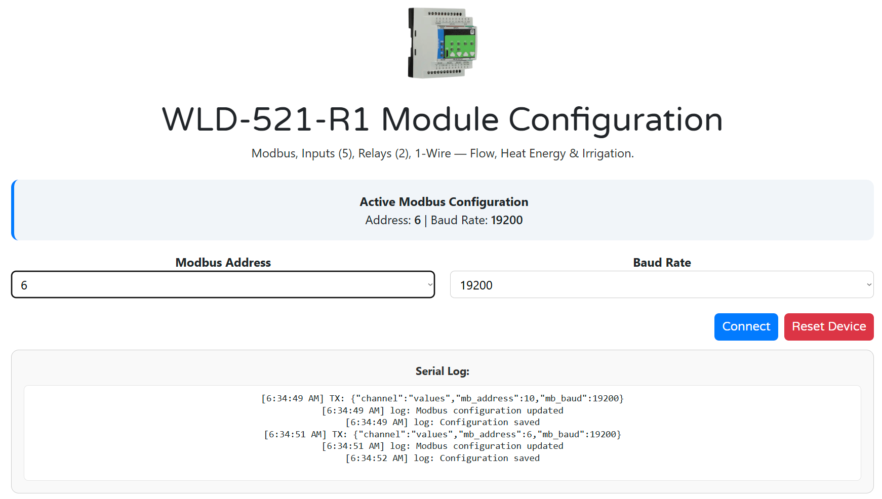
🔌 WebConfig Setup
- Connect the module to your PC using a USB-C cable.
- Open https://www.home-master.eu/configtool-wld-521-r1 in Chrome or Edge.
- Click “Connect” and select the serial device.
- The header will show the Active Modbus Configuration (Address, Baudrate).
You can safely reset or update Modbus settings at any time.
🧩 Modbus Address & Baudrate
In the Modbus panel:
- Set Address (1–255): each module must have a unique address.
- Set Baudrate: choose between 9600–115200 (default: 19200).
- Confirm the updated settings in the banner and Serial Log.
📸 
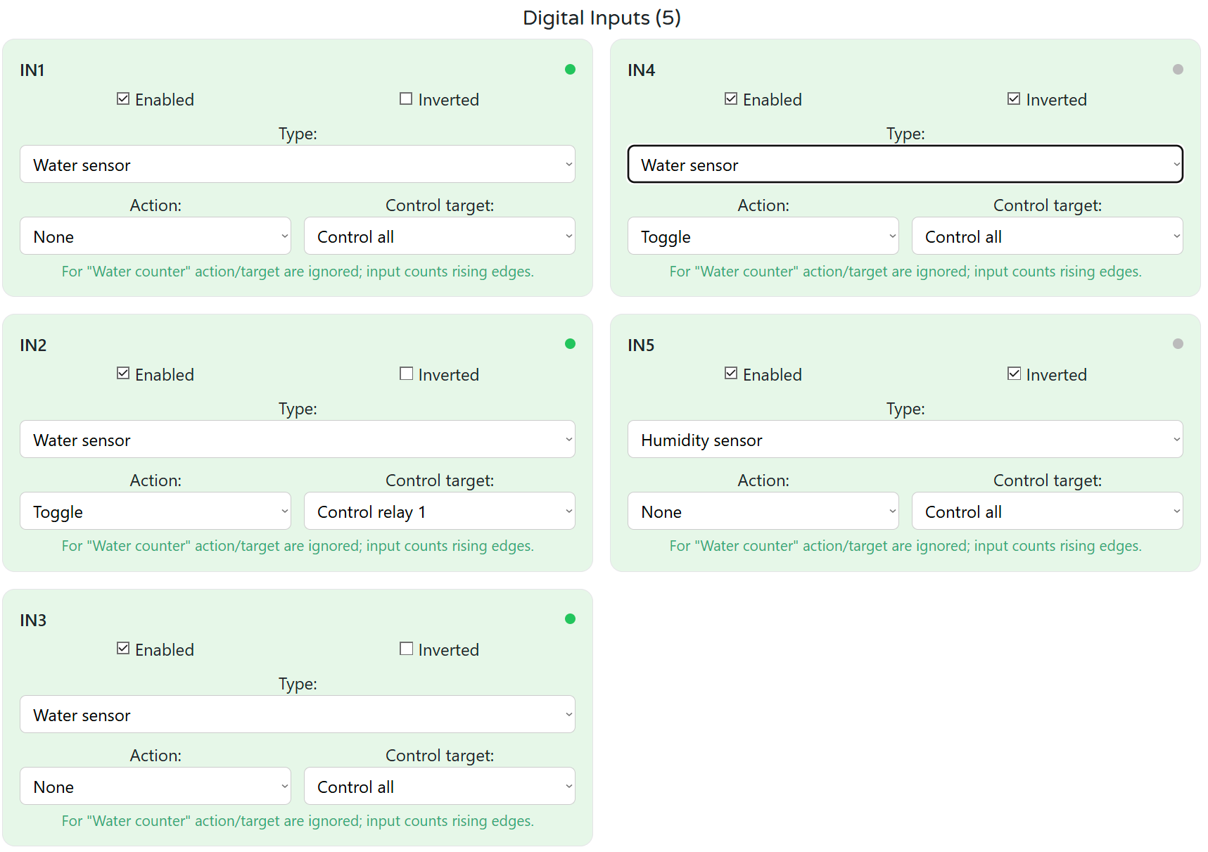
🔁 Input Configuration (DI1–DI5)
Each DI has:
- Enable / Invert
- Type:
Water sensorSoil moistureWater counter(flow meter input)
For Water sensor / Soil moisture:
- Action:
None,Toggle, orPulse
- Control Target:
All,Relay 1,Relay 2,None
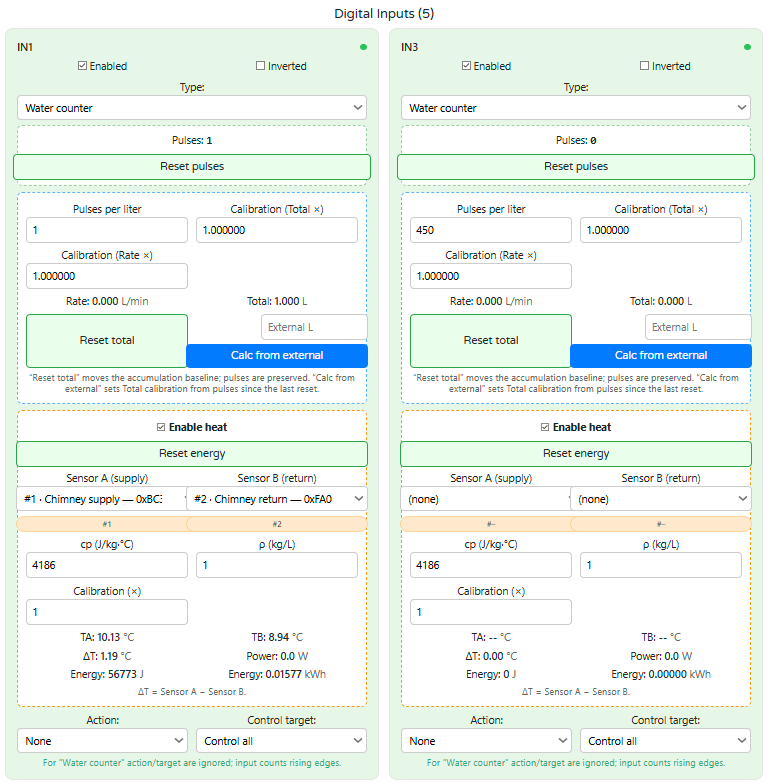
For Water counter:
- Pulses per Liter (PPL): e.g., 450
- Rate × / Total ×: calibration scalars
- Live Flow:
- Rate (L/min)
- Total (L)
- Reset Total / Reset Pulses
- Calc from External: align module total with external meter
📸 
🔥 Heat Energy Calculation (Optional on Counter DIs)
Enable Heat on a DI to calculate:
- ΔT from 1-Wire
Sensor A–Sensor B - Power (W) and Energy (J / kWh) using:
- cp (J/kg·°C), ρ (kg/L), Calibration ×
→ Formula:
Power = cp × ρ × ΔT × FlowRate
Energy = ∑ Power × Δt
You can:
- View TA, TB, ΔT
- Reset energy counters
📸 
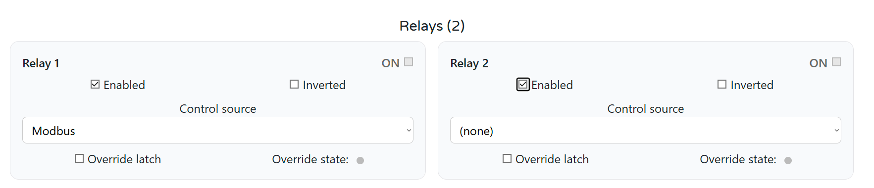
⚙️ Relay Logic Configuration (Relay 1 & 2)
- Enable / Invert
- Control Source:
Modbus,Local Logic, orNone
- Manual Override
- ON/OFF switch
- Latch override to persist across Modbus commands
Relays are dry contact. Wire loads to
NO / NC / COM.
📸 
🔵 LED Mapping (LED1–LED4)
Each LED can be:
- Mode:
SolidorBlink - Source:
DI1–DI5,Relay 1/2,Irrig 1/2,Override R1/R2
The State Dot shows live ON/OFF.
📸 
🔘 Button Configuration (BTN1–BTN4)
Each button triggers an Action:
- Relays:
Toggle R1/R2,Pulse R1/R2
- Irrigation:
Start/Stop Zone 1/2
- Manual Override:
R1/R2 Override Toggle
Button Press Behavior
- Short press = toggle state
- Long press (3s) = enter/exit override mode
- In override, relay ignores Modbus/logic control
📸
🧪 Testing & Diagnostics
Use:
- Serial Log to watch changes live
- Status pills on every component card to view DI/relay/button states
- Reset Device to safely reboot the module
⏰ Clock & Home Assistant Sync
If using irrigation windows or daily counters:
- Use coil 360 =
CMD_TIME_MIDNIGHTto sync at 00:00 - Optionally set:
- Minute of day (
HREG 1100) - Day index (
HREG 1101)
- Minute of day (
This ensures irrigation windows behave predictably and counters roll over cleanly.
✅ WebConfig saves all changes immediately to flash. You can disconnect USB-C after setup — the device runs autonomously and responds to Modbus polling.
4.6 Getting Started
Summarize steps in 3 phases:
- Wiring
- Configuration
- Integration
5. WLD‑521‑R1 — Technical Specification
This section consolidates diagrams, I/O, electrical limits, firmware behavior, connector map, mechanics, and compliance for quick reference.
5.1 Diagrams & Pinouts
System Block Diagram
|
Terminal Map
|
Field Board Layout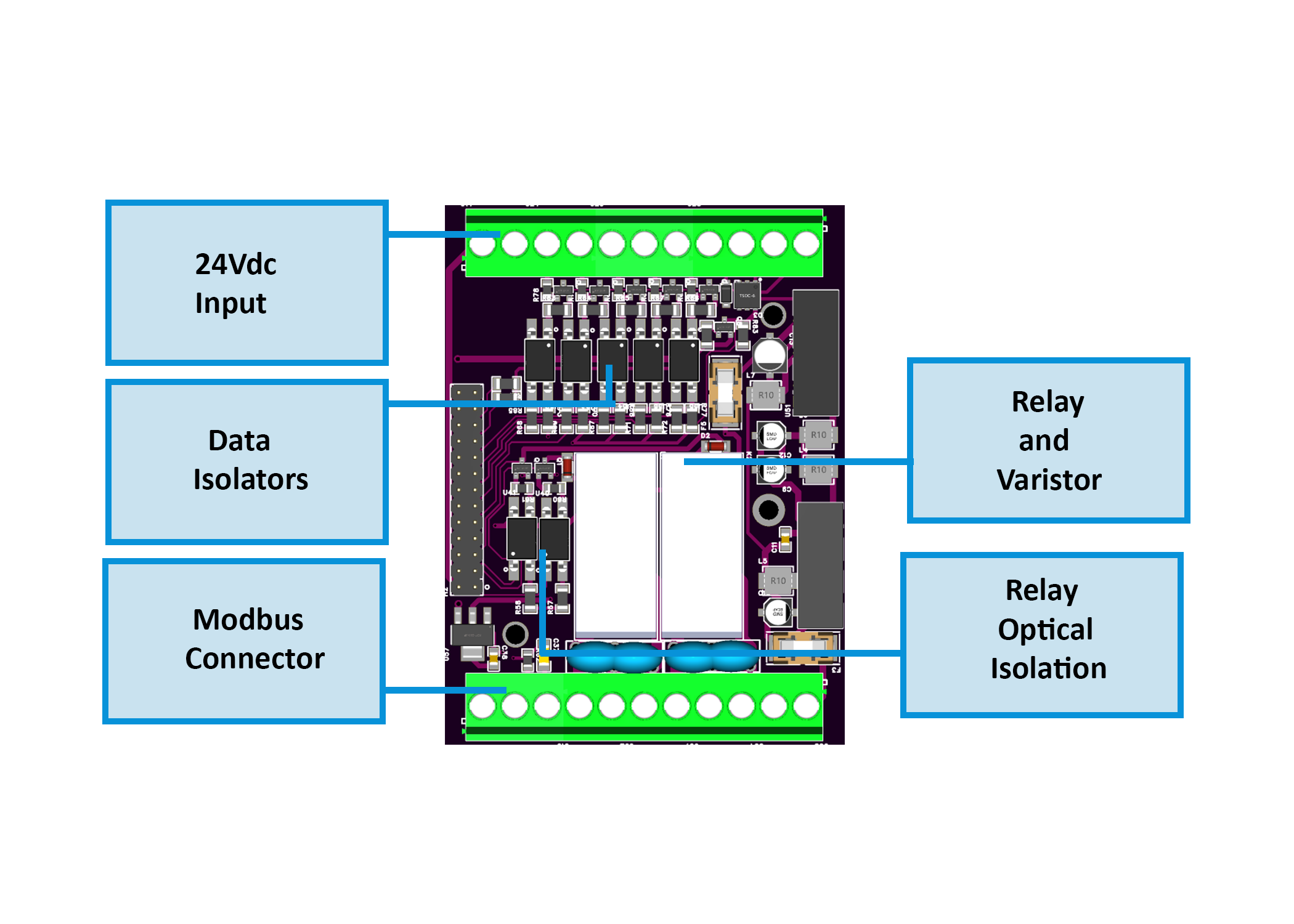
|
MCU Board Layout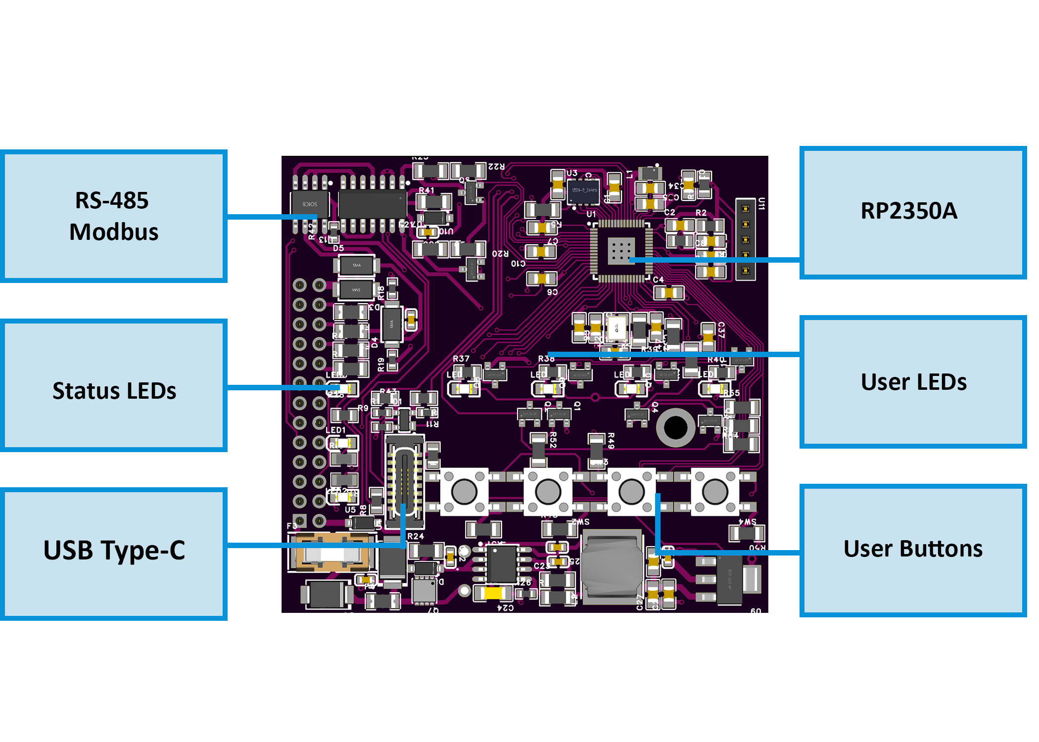
|
5.2 I/O Summary
| Interface | Qty | Description |
|---|---|---|
| Digital Inputs | 5 | Opto‑isolated DI (dry contact / open‑collector / pulse for flow meters); isolated return (GND_ISO). |
| Relay Outputs | 2 | SPDT dry contact (NO/C/NC); snubbered; local/Modbus/logic control. |
| User LEDs | 4 | Configurable (Solid/Blink) for DI/Relay/Irrigation/Override feedback. |
| User Buttons | 4 | Assignable actions (Relay toggle/pulse, Override, Irrigation start/stop). |
| RS‑485 (Modbus) | 1 | Half‑duplex multi‑drop; A/B/COM terminals; fail‑safe & surge‑protected. |
| USB‑C | 1 | Service/setup via WebConfig (Web Serial). |
| 1‑Wire Bus | 1 | +5 V / DATA / GND (logic domain) for DS18B20 sensors. |
| Sensor Power | 2 | Isolated +12 V / +5 V rails for low‑power sensors only (fused, filtered). |
5.3 Electrical Specifications
Power & Rails
| Parameter | Min | Typ | Max | Notes | |—————————–|—–|—–|—–|——| | Supply voltage (V+) | 20 V | 24 V | 30 V | SELV; reverse/surge protected input. | | Power consumption | — | 1.85 W | 3.0 W | Module only (no external loads). | | Logic rails | — | 5 V / 3.3 V | — | Buck + LDO derived. | | Isolated sensor rails | — | +12 V ISO / +5 V ISO | — | Fused, LC‑filtered; for sensors only (≤ ~150 mA shared). | | 1‑Wire bus power | — | +5 V (logic) | — | Non‑isolated, for 1‑Wire devices only. |
Digital Inputs (DI1…DI5)
| Parameter | Value / Behavior | |———————-|——————| | Type | Opto‑isolated; dry contact / open‑collector / pulse. | | Threshold | Low‑voltage, sensor‑level (use GND_ISO return). | | Debounce | Firmware‑controlled. | | Pulse rate (counter) | ~ up to 9–10 Hz practical for flow meters. | | Isolation | Field domain to logic via opto barrier. |
Relay Outputs (R1, R2)
| Parameter | Value / Behavior | |———————-|——————| | Type | SPDT, dry contact (NO/C/NC). | | Ratings (contacts) | 250 VAC 16 A (cosφ=1), 250 VAC 9 A (cosφ=0.4), 30 VDC 10 A. | | Protection | RC / varistor snubbers for inductive loads. | | Recommendation | Use coupling relays for inductive or >5 A continuous loads. |
Communications
| Interface | Details | |———-|———| | RS‑485 | Modbus RTU, half‑duplex; 9600–115200 bps (default 19200, 8N1); fail‑safe, short‑circuit limited, surge‑protected. | | USB‑C | USB 2.0 device for WebConfig (setup only); ESD‑protected; CP2102N bridge. |
Environment & Compliance
| Parameter | Value | |—————————-|——-| | Operating temperature | 0…40 °C | | Humidity | ≤95 % RH, non‑condensing | | Ingress / Safety class | IP20; Operation Type 1 | | Rated impulse (outputs) | 2.5 kV | | Max altitude / pollution | 2000 m / Degree 2 |
5.4 Firmware Behavior
Input → Action & Alarm Logic
- DI Types: Water sensor, Soil moisture, Water counter (flow).
- Enable / Invert per channel; debounce configurable.
- Non‑counter actions:
None,Toggle,Pulsewith Control Target (Relay 1,Relay 2,All,None). - Counter channels: set Pulses per Liter (PPL), Rate× / Total× calibration; expose Rate (L/min) & Total (L).
- Heat energy (optional): enable on a counter; assign 1‑Wire Sensor A/B; set cp (J/kg·°C), ρ (kg/L), and Calibration×.
Power (W) = cp × ρ × ΔT × FlowRateEnergy = ∑ Power × Δt- Live values: TA, TB, ΔT, Power, Energy; Reset available.
Relay Ownership & Overrides
- Control Source per relay:
Modbus(default),Local Logic(e.g., irrigation), orNone. - Override: immediate ON/OFF with Latch option; override state supersedes Modbus and local logic until cleared.
- Safety: relays are dry contact; external loads must be powered from a separate supply.
LEDs & Buttons
- LEDs (4): map to DI, Relays, Irrigation Zones, or Override; Solid or Blink modes.
- Buttons (4): assign
Toggle/Pulse R1/R2,Override Toggle R1/R2,Irrigation Zone 1/2 Start/Stop.- Short press: action (toggle/pulse).
- Long press (~3 s): enter/exit override mode for the mapped relay.
Modbus Defaults & Persistence
- Defaults: Address
3, Baud19200, 8N1. - WebConfig: all changes apply live and are persisted to flash.
- Daily sync: optional midnight sync (coil 360) for counters/windows when used with Home Assistant.
5.5 Absolute Electrical Specifications
| Parameter | Min | Typ | Max | Notes |
|---|---|---|---|---|
| Supply voltage (V+) | 20 V | 24 V | 30 V | SELV; reverse/surge protected input. |
| Power consumption | — | 1.85 W | 3.0 W | Module only (no external loads). |
| Logic rails | — | 5 V / 3.3 V | — | Buck + LDO derived. |
| Isolated sensor rails | — | +12 V ISO / +5 V ISO | — | Fused & LC‑filtered; specify budget per install. |
| Digital inputs | — | — | — | Opto‑isolated; per‑channel surge protection. |
| Relay contacts (R1–R2) | — | — | 250 VAC 16 A / 30 VDC 10 A | Use external snubbers; derate for inductive loads. |
| RS‑485 interface | — | 115200 bps | — | Half‑duplex; fail‑safe; short‑circuit limited; surge‑protected. |
| USB‑C | 5 V | — | — | USB 2.0 device; ESD‑protected; setup only. |
| Operating temperature | 0 °C | — | 40 °C | ≤95 % RH, non‑condensing. |
Installer note: Fuse the 24 VDC feed upstream and add RC/TVS snubbers for inductive loads (pumps, valves).
5.6 Connector / Terminal Map (Field Side)
External terminals are 5.08 mm pitch pluggable blocks (300 V / 20 A, 26–12 AWG, torque 0.5–0.6 Nm).
| Block / Label | Pin(s) (left → right) | Function / Signal | Limits / Notes |
|---|---|---|---|
| POWER | V+, 0V |
24 VDC SELV input | Reverse & surge protected; fuse upstream. |
| DIGITAL INPUTS – TOP | I1…I5, GND (ISO) |
DI1…DI5 with isolated return | Keep returns on GND_ISO; dry‑contact/open‑collector only. |
| RELAY1 | NO, C, NC |
SPDT dry contact | Follow front label order. |
| RELAY2 | NO, C, NC |
SPDT dry contact | Follow front label order. |
| RS‑485 (bottom left) | B, A, COM |
Modbus RTU bus | Match A/B polarity; COM = reference GND; terminate bus ends. |
| 1‑WIRE (top right) | +5V, D, GND |
1‑Wire bus (logic domain) | For DS18B20; not isolated from logic. |
| SENSOR POWER (bottom right) | +5 V ISO, +12 V ISO, GND_ISO |
Isolated sensor rails | For sensors only; fused; no actuators. |
| USB‑C (front) | — | Web‑Serial config | ESD‑protected; not a field power source. |
5.7 Mechanical Details
- Mounting: DIN rail EN 50022, 35 mm
- Enclosure: PC/ABS, V‑0, light gray/black, matte
- Terminals: 5.08 mm pitch; 26–12 AWG (to 2.5 mm²); 0.5–0.6 Nm torque
5.8 Environmental & Compliance
- Operating temperature: 0…40 °C; Humidity: ≤95 % RH (non‑condensing)
- Ingress / Safety class: IP20; Operation Type 1
- Impulse / Altitude / Pollution: 2.5 kV rated impulse (digital output), max altitude 2000 m, Pollution degree 2
- Installation: SELV only; by qualified personnel per local codes
6. Modbus RTU Communication
The WLD‑521‑R1 communicates as a Modbus RTU slave over RS‑485, exposing its digital inputs, counters, flow data, heat metrics, relays, LEDs, irrigation state, and 1‑Wire temperatures.
6.1 Modbus Basics
| Parameter | Value |
|---|---|
| Interface | RS‑485 (half-duplex) |
| Baudrate | 9600–115200 (default: 19200) |
| Address | 1–255 (default: 3) |
| Parity | 8N1 |
| Role | Slave (responds to master requests) |
| Supported FCs | 0x01 Read Coils, 0x02 Read Discrete Inputs, 0x03 Read Holding, 0x04 Read Input, 0x05/0x0F Write Coils, 0x06/0x10 Write Holding |
🧩 Address and baudrate are configured via USB-C using WebConfig.
6.2 Address Map Overview
| Function | Range | Description |
|---|---|---|
| Coils (FC01/05) | 200–399 |
Control commands: relay ON/OFF, irrigation, reset |
| Discrete Inputs (FC02) | 1–103 |
Real-time state of DI, relays, LEDs, buttons |
| Holding Registers (FC03/16) | 1100+ |
Flow, temperature, energy, configuration |
| Input Registers (FC04) | same as holding | Optional mirror of Holding (read-only) |
6.3 Coils (Write – Single/Multiple)
| Coil Address | Description |
|---|---|
| 200–201 | Relay ON (Relay 1/2) |
| 210–211 | Relay OFF (Relay 1/2) |
| 300–304 | Enable DI1…DI5 |
| 320–324 | Disable DI1…DI5 |
| 340–344 | Reset DI counter |
| 360 | CMD_TIME_MIDNIGHT (pulse at 00:00 to sync time) |
| 370–371 | Irrigation START Z1/Z2 |
| 380–381 | Irrigation STOP Z1/Z2 |
| 390–391 | Irrigation RESET Z1/Z2 |
Coils are pulse-operated (write
TRUE, thenFALSE).
Manual overrides may block Modbus control until cleared.
6.4 Discrete Inputs (Read-only Flags)
| Address | Bit | Function |
|---|---|---|
| 1–5 | 1–5 | DI1…DI5 (debounced) |
| 60–61 | — | Relay 1/2 state |
| 90–93 | — | LED1…LED4 (mapped source ON) |
| 100–103 | — | BTN1…BTN4 (pressed = 1) |
6.5 Holding Registers (Read/Write)
These registers expose flow, heat, irrigation state, 1‑Wire temperatures, and runtime status.
📊 Input / Flow / Energy Registers
| Address | Description | Format | Unit | Notes |
|---|---|---|---|---|
| 1100 | Minute of day | U16 |
min (0–1439) | Local module clock |
| 1101 | Day index | U16 |
days | Increments daily |
Flow Rate & Totals (per DI1–5)
| Address | Description | Format | Notes |
|———|————-|——–|——-|
| 1120–1129 | Flow rate (L/min ×1000) | U32 ×5 | 2 registers each |
| 1140–1149 | Flow total (L ×1000) | U32 ×5 | 2 registers each |
Heat Energy (if enabled)
| Address | Description | Format | Notes |
|———|————-|——–|——-|
| 1200–1209 | Power (W) | S32 ×5 | ΔT × cp × ρ × flow |
| 1220–1229 | Energy (Wh ×1000) | U32 ×5 | Accumulator |
| 1240–1249 | ΔT (°C ×1000) | S32 ×5 | TA–TB |
🌱 Irrigation Zones (Z1 / Z2)
| Address | Description | Format |
|---|---|---|
| 1300–1301 | Zone state (0=idle, 1=run, 2=alarm) | U16 |
| 1310–1313 | Accumulated liters | U32 |
| 1320–1323 | Elapsed time (s) | U32 |
| 1330–1333 | Flow rate (L/min ×1000) | U32 |
| 1340–1341 | Window Open flag | U16 |
| 1342–1343 | Sensors OK flag | U16 |
🌡 1-Wire Temperatures
| Address | Description | Format | Notes |
|---|---|---|---|
| 1500–1519 | Temp #1…#10 (°C ×1000) | S32 |
2 regs per sensor |
6.6 Register Use Examples
✅ Read DI1 flow total
- Read
HREG 1140/1141(2x U16 = U32) - Divide result by 1000 → Liters
✅ Reset DI3 pulse counter
- Write
TRUE→ Coil343 - Then write
FALSEto return
✅ Start irrigation on Zone 1
- Write
TRUE → FALSEto coil 370
✅ Sync module time from Home Assistant
- Write
0toHREG 1100at midnight - Pulse
coil 360to trigger time sync
6.7 Polling Recommendations
| Data Type | Suggested Rate | Notes |
|---|---|---|
| DI / Relay / LED / Button | 1 s | Coils, discrete inputs |
| Flow / Counters | 2–5 s | Holding or input regs |
| 1‑Wire Temps | 10–20 s | Poll less frequently to avoid bus errors |
| Irrigation state | 1–2 s | Needed if controller drives automation |
| Heat power/energy | 5–10 s | Internal logic updates per cycle |
6.8 Full Register Summary
Discrete Inputs (FC02)
00001–00005: DI1–DI5 state00060–00061: Relay 1/2 mirror00090–00093: LED state mirror00100–00103: Button press flags
Coils (FC01/05)
00200–00201: Relay ON00210–00211: Relay OFF00300–00304: Enable DI00320–00324: Disable DI00340–00344: Reset DI Counter00360: CMD_TIME_MIDNIGHT00370–00371: Irrigation START00380–00381: Irrigation STOP00390–00391: Irrigation RESET
Holding/Input Registers (FC03/04)
01100–01101: Clock01120–01129: Flow rates01140–01149: Flow totals01200–01209: Heat power01220–01229: Heat energy01240–01249: ΔT01300–01301: Irrigation state01310–01313: Irrigation liters01320–01323: Irrigation elapsed01330–01333: Irrigation flow rate01340–01343: Window & sensor status01500–01519: 1-Wire temperatures
💡 All scaling is based on ×1000 (flow, temp, energy). Use ESPHome or controller math to convert to engineering units.
7. ESPHome Integration Guide
The WLD‑521‑R1 works seamlessly with ESPHome through the HomeMaster MiniPLC/MicroPLC, acting as a Modbus master. The module exposes all I/O and telemetry via Modbus RTU, which ESPHome maps into entities for Home Assistant.
7.1 ESPHome YAML Setup
Here is a typical ESPHome configuration that connects the controller to the WLD‑521‑R1 via RS‑485:
uart:
  id: uart_modbus
  tx_pin: 17
  rx_pin: 16
  baud_rate: 19200
  parity: NONE
  stop_bits: 1

modbus:
  id: modbus_bus
  uart_id: uart_modbus

packages:
  wld1:
    url: https://github.com/isystemsautomation/homemaster-dev
    ref: main
    files:
      - path: WLD-521-R1/Firmware/default_wld_521_r1_plc/default_wld_521_r1_plc.yaml
        vars:
          wld_prefix: "WLD#1"
          wld_id: wld_1
          wld_address: 4     # Match this with WebConfig address
    refresh: 1d
Replace
wld_addresswith your module’s actual Modbus ID (default is3).
You can add more modules by duplicating the package block with uniquewld_id,wld_address, andwld_prefix.
7.2 Exposed Entities (via ESPHome)
🔧 Binary Sensors
DI1toDI5— leak detection, float switch, or pulse edges- Relay mirror (read-only)
- Buttons (
BTN1–BTN4) — short press detection - Irrigation: Zone state, sensor OK flags, window status
📊 Sensors
- Flow rate (L/min) and total (liters) per DI
- 1-Wire temperature probes (°C)
- ΔT, Power (W), Energy (Wh/kWh) for heat metering
- Irrigation: elapsed time, total liters, real-time flow
🔀 Switches
- Relay 1 and Relay 2
- Optional: expose override toggles as separate switches
- Irrigation zone start/stop (via internal helpers or scripts)
7.3 Home Assistant Tips
- Use ESPHome + Home Assistant integration to auto-discover the controller and all WLD entities.
- In ESPHome > Services, call
esphome.device_name_switch.turn_onfor internal switches (likeMidnight pulse). - Create automations:
- At
00:00, pulse coil 360 to reset daily irrigation state. - On leak detection (
DI1=ON), turn on relay/siren and notify. - If
FlowX Ratedrops to 0 during irrigation, stop zone and alert.
- At
Suggested Cards
- Entities card: DI inputs, relays, override status
- Gauge/Stat card: Flow totals, ΔT, or Energy
- History graph: Flow rate, Irrigation status
- Button card: Zone Start/Stop via internal switch helpers
7.4 Troubleshooting
| Problem | Fix |
|---|---|
| No entities show | Check RS‑485 wiring, A/B polarity, and COM ground |
| Coil writes fail | Make sure relay isn’t in override or owned by irrigation logic |
| Midnight reset missing | Add automation to pulse coil 360 nightly |
| Wrong DI naming | Use wld_prefix in packages: to namespace entities uniquely |
| Flow stuck at 0 | Confirm flow DI is in Water counter mode and receiving pulses |
7.5 Compatibility
| Platform | Status |
|---|---|
| ESPHome 2025.8+ | ✅ Supported |
| Home Assistant | ✅ via ESPHome integration |
| Multiple WLDs | ✅ supported via multiple packages: |
Always ensure the controller’s YAML uses the correct
uart,modbus, andwld_address. One misalignment can break polling.
8. Programming & Customization
8.1 Supported Languages
- Arduino
- C++
- MicroPython
8.2 Flashing
- Connect via USB-C to a computer using Chrome/Edge browser or a serial flasher.
- To enter bootloader mode, press and hold Buttons 1+2, then release while connecting power.
- To trigger a hardware reset, press and hold Buttons 3+4 for 3 seconds.
- Use PlatformIO or Arduino IDE with appropriate RP2040 board profile.
8.3 Arduino / PlatformIO Notes
- Board config: Use Generic RP2040 or RP2040-based custom board with QSPI.
- Flash size: 2 MB Flash (Sketch: 1MB, FS: 1MB)
- Required Libraries:
Arduino.hModbusSerial.hSimpleWebSerial.hArduino_JSON.hLittleFS.hOneWire.hhardware/watchdog.h
- Pin Mapping is aligned with RP2350 definitions; see schematic for GPIO layout.
8.4 Firmware Updates
- Use WebConfig or USB-C to re-flash the firmware using the appropriate boot/reset combination.
- Configuration is stored in persistent flash (retained across firmware upgrades).
- If a flash fails, enter BOOT mode manually and retry via browser uploader or PlatformIO CLI.
- WebConfig can restore base config with default values if corrupted.
8. Programming & Customization
This section matches the style shown in your screenshot and includes the missing items (MicroPython note, USB‑C flashing steps, button reference image, and Arduino include list).
8.1 Supported Languages
- MicroPython
- C/C++
- Arduino IDE
8.2 Flashing via USB‑C
- Connect USB‑C from PC to the module.
- Enter boot/flash mode if required (see combinations below).
- Upload the provided firmware (WebConfig Uploader, PlatformIO, or Arduino IDE).
Boot/Reset combinations (handled in hardware):
- Buttons 1 + 2 → forces the module into BOOT mode.
- Buttons 3 + 4 → triggers a hardware RESET.
Use these combinations during firmware flashing or to restart the device manually.
Button numbering reference:
8.3 Arduino / PlatformIO Notes
- Board profile:
Generic RP2350(RP2 family, dual‑core) - Flash layout: 2 MB total (suggested Sketch: 1 MB, FS: 1 MB)
- Toolchains: Arduino IDE 2.x or PlatformIO (
platform = raspberrypi)
Required libraries (typical project):
Arduino.hModbusSerial.hSimpleWebSerial.hArduino_JSON.hLittleFS.hOneWire.hhardware/watchdog.h
8.4 Firmware Updates
To update the firmware, use the Arduino IDE or PlatformIO via USB‑C:
- Connect the USB‑C cable to the module.
- Press Buttons 1 + 2 together to enter BOOT mode, re‑connect USB‑C, and re‑flash. Use Buttons 3+4 for a hard reset.
- Upload the updated binary located in
Firmware/default_wld_521_r1/.
9. Maintenance & Troubleshooting
9.1 Status LED Meanings
| LED | Meaning |
|---|---|
| PWR | Steady ON = power OK |
| TX/RX | Blink on RS‑485 activity |
| USB | Lit when WebConfig is connected |
| LED1–4 | Mapped per UI config (DI/Relay/Irrigation/Override) |
9.2 Reset Methods
- Soft reset: WebConfig → Reset Device
- Hard reset: hold Buttons 3 + 4 for ~3 s
- Bootloader: hold Buttons 1 + 2 while powering the device
9.3 Common Issues
| Symptom | Likely Cause → Fix |
|---|---|
| No Modbus comms | A/B swapped, missing COM reference, wrong baud/address |
| Relay won’t trigger | Relay in override, or Owner set to None/Logic |
| Flow stays 0 | DI not set to Water counter, wrong PPL, no pulses |
| 1‑Wire not found | Wiring to +5V/D/GND, long bus, or pull‑up issue |
| WebConfig not connecting | Use Chrome/Edge; close other serial apps; try new cable/port |
10. Open Source & Licensing
Licensing
This project uses a hybrid licensing model.
Hardware
Hardware designs (schematics, PCB layouts, BOMs) are licensed under: CERN-OHL-W v2
Firmware & ESPHome Integration
All firmware, ESPHome configurations, and software components are licensed under: MIT License
This ensures full compatibility with ESPHome and Home Assistant while protecting hardware designs.
See LICENSE files in each directory for full terms.
11. Downloads
- Firmware binaries —
Firmware/default_wld_521_r1/ - ESPHome YAML configs —
Firmware/default_wld_521_r1_plc/ - WebConfig Tool —
Firmware/ConfigToolPage.html - Schematics —
Schematics/WLD-521-R1-FieldBoard.pdf,Schematics/WLD-521-R1-MCUBoard.pdf - Images & diagrams —
Images/ - Datasheet —
Manuals/WLD-521-R1 Datasheet.pdf
12. Support
- Support Portal: https://www.home-master.eu/support
- WebConfig: https://www.home-master.eu/configtool-wld-521-r1
- YouTube: https://youtube.com/@HomeMaster
- Hackster: https://hackster.io/homemaster
- Reddit: https://reddit.com/r/HomeMaster
- Instagram: https://instagram.com/home_master.eu