homemaster-dev
🚧 Project Status: Under Active Development & Testing
Important Notice: This documentation, hardware designs, and firmware are for the pre-release version of the HomeMaster system. All information is preliminary and may contain errors or be subject to change.
- Hardware: Modules are currently in the prototyping and testing phase. Final production versions may differ.
- Firmware: Firmware is under active development and is considered beta. Features, configurations, and stability are being refined.
Please use this information for evaluation and development purposes only. Check the Releases page for the latest stable versions and updates.
Firmware Version: 2025-10 snapshot
ALM-173-R1 Module for Alarm Systems
1. Overview & Description
The ALM-173-R1 is a configurable alarm I/O module for intrusion detection, fault annunciation, and local supervision. It integrates with a MicroPLC/MiniPLC or any Modbus master over RS-485 (Modbus RTU) and is configured via a USB-C WebConfig UI (Web Serial).
Highlights
- I/O: 17 opto-isolated digital inputs, 3 SPDT relays
- Local HMI: 4 buttons (ack/override) and 4 LEDs (status/alert)
- Interface: RS-485 (Modbus RTU), address 1–255, 9600–115200 baud
- Setup: Web browser (Chromium) via USB-C WebConfig; live status + safe device reset
- Design: Galvanically isolated field side; RP2350 MCU with MAX485 and PCF8574 expanders; powered from 24 VDC
- Integration: Modbus map exposes inputs, alarm/group bits, and relay states (works smoothly with Home Assistant / PLC / SCADA)
Quick use case: wire inputs → assign to alarm groups → choose Active-while or Latched-until-ack → map groups to relays/LEDs → connect RS-485 → acknowledge locally or via Modbus.
Core Capabilities
| Subsystem | Qty | Description |
|---|---|---|
| Digital Inputs | 17 | Dry contact / isolated LV; per-input Enable, Invert, debounce, Group (1/2/3) |
| Relays | 3 (SPDT) | Follow alarm Group, Master (Modbus), or Manual Override; invert/enable per channel |
| Alarm Groups | 3 + Any | Modes: Active-while (momentary) or Latched-until-ack |
| User Buttons | 4 | Ack All, Ack G1–G3, or Relay 1–3 override |
| User LEDs | 4 | Steady/Blink; sources: Any, G1–G3, or Relay override |
| Config UI | — | WebConfig via USB-C (Web Serial): Modbus addr/baud, mapping, live status, reset |
| Modbus RTU | RS-485 | Multi-drop slave; Address 1–255, 9600–115200 baud |
| MCU | RP2350 + QSPI | Dual-core MCU with external flash; resilient field I/O control |
| Power | 24 VDC | 24→5→3.3 V regulators + isolated sensor rails (+12 V, +5 V) |
| Protection | — | TVS, PTC, and ESD protection on field connections |
System Role & Communication
| Item | Details |
|---|---|
| Role | Standalone Modbus slave running local group/ack logic; mirrors states to PLC/SCADA |
| Position | Expansion module on RS-485 trunk (A/B/COM) |
| Default Modbus ID | 3 (change per installation) |
| USB-C | Setup/diagnostics with Chromium browser |
| Daisy-chain | Multiple ALMs on the same bus with unique IDs |
2. ALM-173-R1 — Technical Specification
2.1 Diagrams & Pinouts
| ALM System Diagram | RP2350 MCU Pinout |
|---|---|
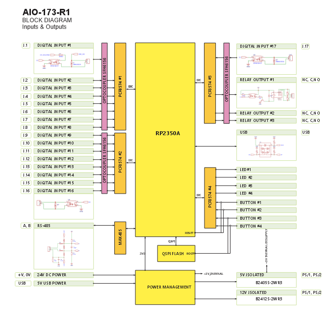 |
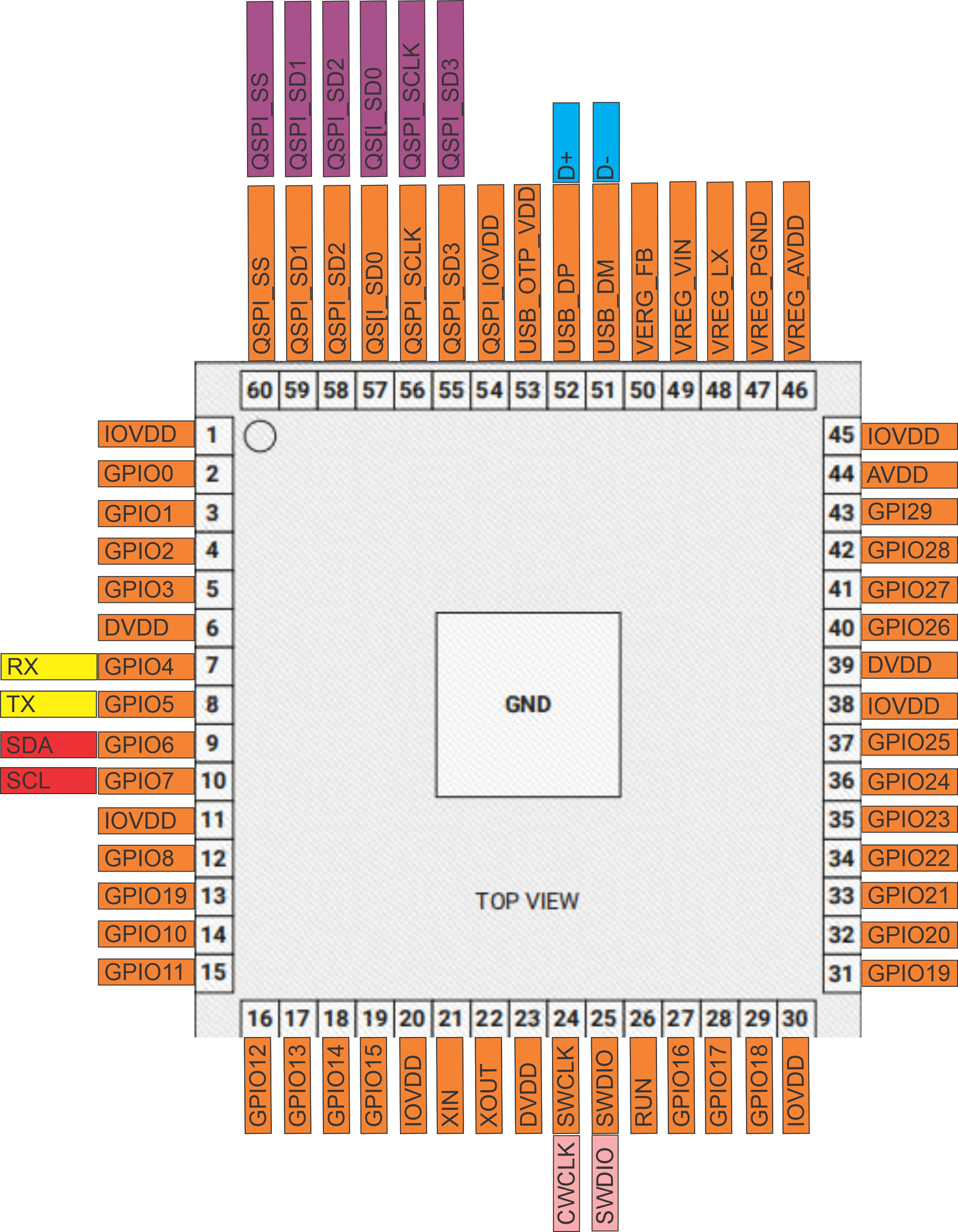 |
| Field Board Layout | MCU Board Layout |
|---|---|
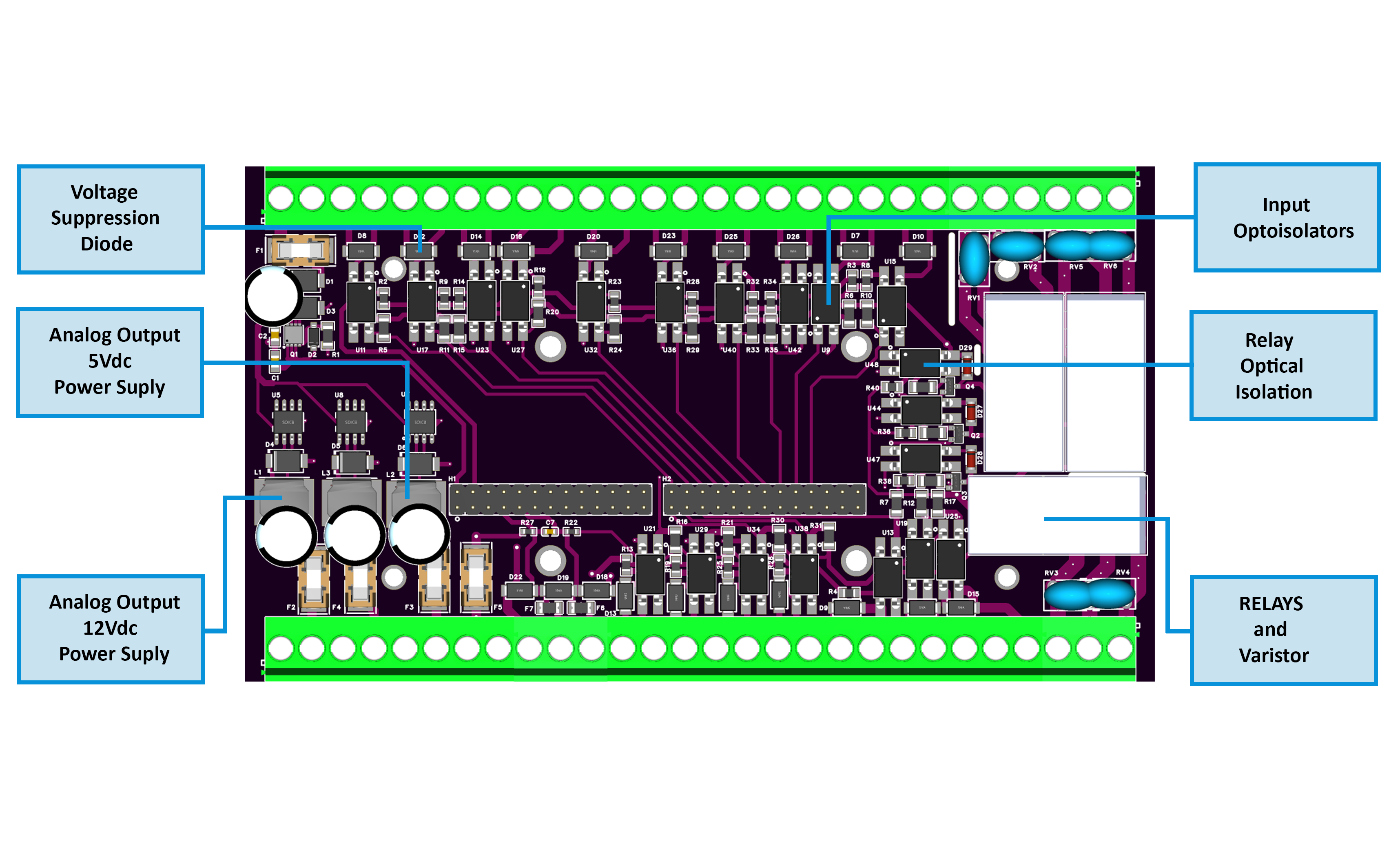 |
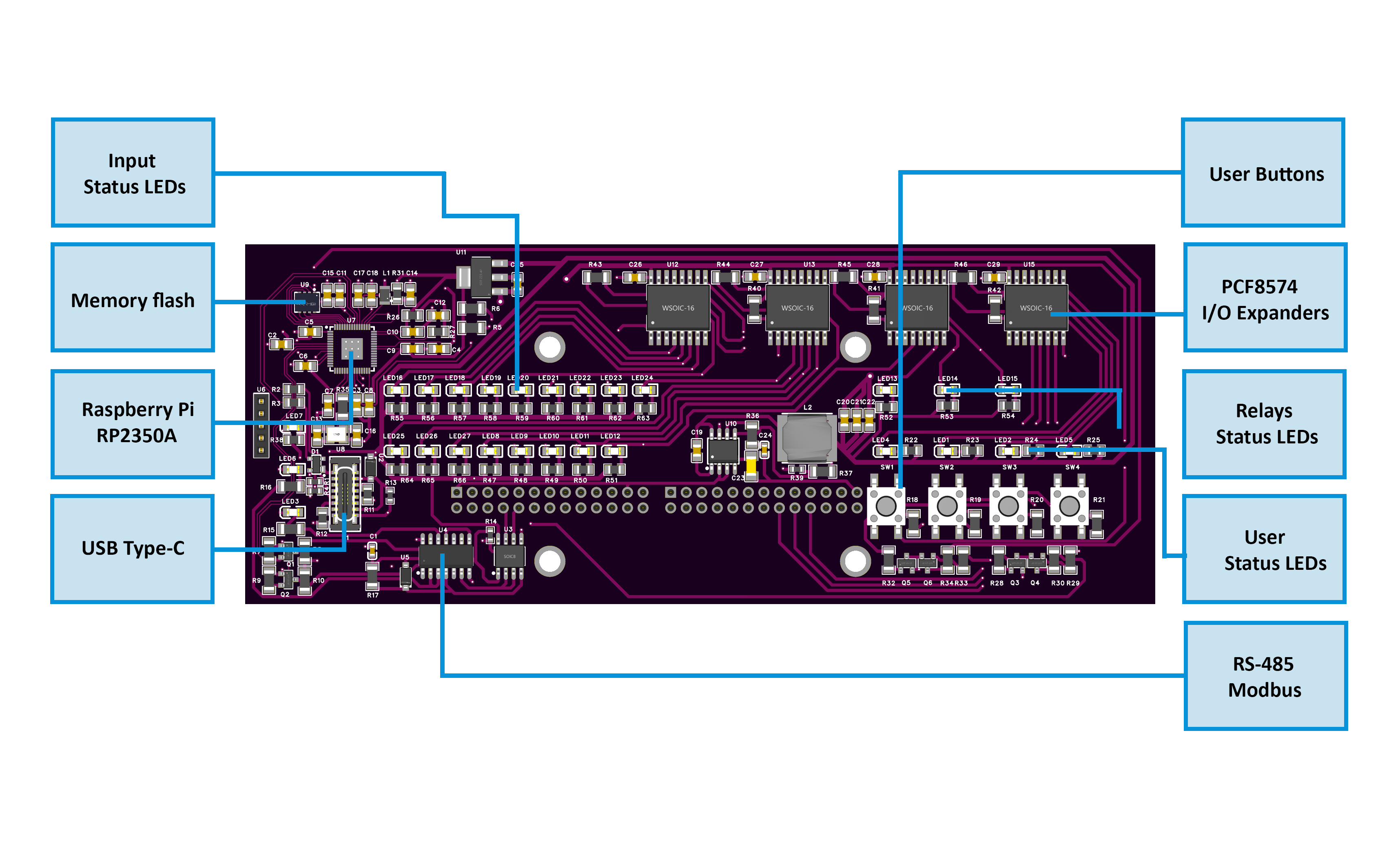 |
2.2 Quick Overview
- Function: Alarm/annunciator I/O with 17 opto DI + 3 SPDT relays
- Interface: RS-485 (Modbus RTU); address 1–255; 9.6–115.2 kbps
- Form factor: DIN-rail; USB-C service (Web Serial config)
- Local HMI: 4 buttons (ack/override), 4 LEDs (status/alert)
2.3 I/O Summary
| Interface | Qty | Electrical / Notes | |—|—:|—| | Digital Inputs (IN1…IN17) | 17 | Opto-isolated to GND_ISO; dry contact / isolated LV; debounce/invert/group in firmware. | | Relays (RLY1…RLY3) | 3 | SPDT COM/NO/NC; can follow alarm groups, master, or manual override. | | Isolated Sensor Rails | 2 | +12 V (PS/1), +5 V (PS/2); isolated & fuse-limited (sensors only). | | User Buttons | 4 | Ack All / Ack G1–G3 / Relay overrides (configurable). | | User LEDs | 4 (+PWR/TX/RX) | Map to Any/G1–G3/Overrides; Steady/Blink; TX/RX show bus activity. | | Field Bus | 1 | RS-485 A/B/COM with protection and fail-safe bias. | | Service | 1 | USB-C (config/diagnostics). |
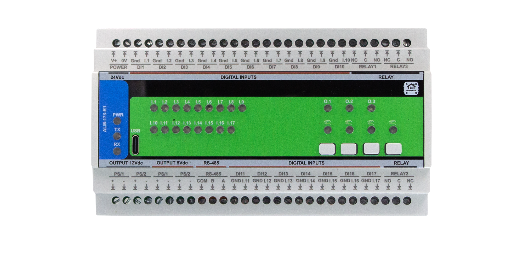
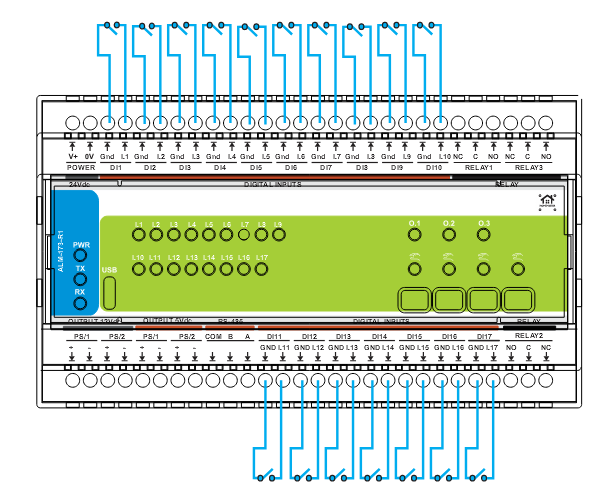
2.4 Terminals & Pinout (Field Side)
Blocks:
- POWER: V+, 0V (24 VDC SELV)
- DI1…DI17: each with paired GND_ISO returns
- RELAY1 / RELAY3 (top): NC-C-NO; RELAY2 (bottom): NO-C-NC
- PS/1 (+12 V ISO) / PS/2 (+5 V ISO): sensors only (fused)
- RS-485: COM, B, A
- USB-C: service (not a load supply)
5.5 Electrical & MCU (Condensed)
- Power path: 24 VDC in → buck 5 V → LDO 3.3 V; isolated +12 V / +5 V rails for sensors
- Inputs: opto-isolated, protected; per-channel Enable / Invert / Group (1–3/None)
- Relays: HF115F drivers with isolation; onboard suppression; use external RC/TVS for inductive loads
- RS-485: MAX485-class with TVS/PTC; TX/RX indicators; half-duplex RTU
- USB-C: ESD/EMI protection; Web-Serial config only
- MCU/Storage: RP2350A dual-core + W25Q32 QSPI; I/O expanders PCF8574
2.6 Key Ratings
| Parameter | Min | Typ | Max | Notes | |—|—:|—:|—:|—| | Supply (V+) | 20 V | 24 V | 30 V | SELV, protected input | | Power (module) | — | 1.85 W | 3.0 W | No external loads | | Relays (contacts) | — | — | — | 250 VAC 16 A (cosφ=1), 30 VDC 10 A; derate for inductive | | RS-485 speed | — | — | 115.2 kbps | 8N1 | | Operating temp | 0 °C | — | 40 °C | ≤95% RH, non-condensing |
2.7 Mechanical & Compliance
- DIN-rail: EN 50022, 35 mm; PC/ABS V-0 enclosure
- Size / mass: 157.4 × 91 × 58.4 mm, ~420 g
- Dimensions drawing:
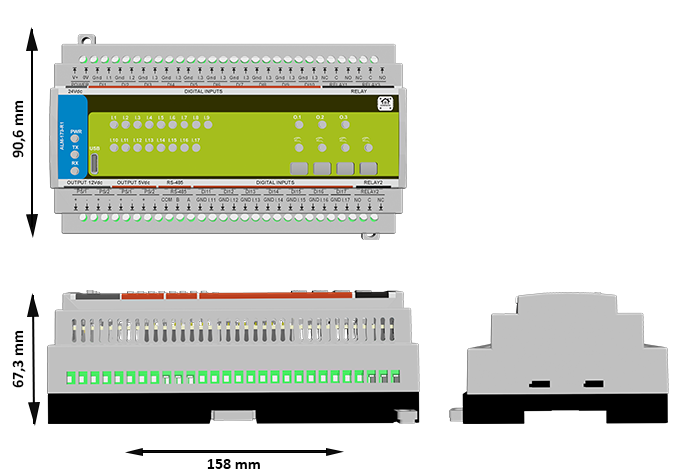
- Environmental: IP20, Type 1; impulse 2.5 kV; altitude ≤ 2000 m; pollution degree 2
2.8 Protections & Firmware (Brief)
- Protections: reverse/TVS on 24 V, isolated sensor rails with PTCs, TVS on RS-485/USB, opto isolation on I/O, contact snubbers onboard
- Alarm engine: Inputs → G1–G3 (Active-while / Latched-until-ack) + Any Alarm; relays can follow groups/master/override; LEDs/buttons configurable; Modbus map exposes states & controls
3. Use Cases 🛠️
These are practical examples of deploying the ALM-173-R1 with the HomeMaster Mini/Micro PLC or any Modbus RTU master.
Each case uses built-in firmware features via the Web Serial UI:
- Input settings: Enable, Invert, Group
- Relay logic: Enable, Invert, Group or Manual
- Alarm behavior: Latched or Momentary
- Buttons & LEDs: Ack / Override / Status
- Modbus: PLC reads status and controls relays
1) [Intrusion] Zone Alarm with Siren (Latched)
Trigger a siren when a sensor activates. Alarm stays ON until acknowledged.
Steps:
- Map IN1 → Group 1; enable + invert if NC.
- Set Group 1 → Latched until acknowledged.
- Map Relay 1 → Group 1 (enable; invert if required).
- Set Button 1 → Acknowledge Group 1.
- Set LED 1 → Group 1, Blink mode.
- PLC reads Group 1 + “Any Alarm” status.
2) [Access Control] Dual-Door Alarm with Shared Strobe
Two zones, each with own buzzer. Common strobe flashes on any alarm.
Steps:
- Map IN1 → Group 1, IN2 → Group 2.
- Set Groups 1 & 2 → Latched.
- Map Relay 1 → Group 1, Relay 2 → Group 2.
- PLC toggles Relay 3 when “Any Alarm” is active.
- Set Button 1 → Ack G1, Button 2 → Ack G2.
- Set LEDs 1–3 → G1, G2, Any Alarm.
3) [Supervision] Equipment Room Summary Alarm
Aggregate faults (smoke, thermal, flood, etc.) into one visual + Modbus alarm.
Steps:
- Map IN1–IN8 → Group 1, invert per sensor.
- Set Group 1 → Active while condition is active.
- Map Relay 1 → Group 1 (to stack light).
- Set LED 1 → Any Alarm, Blink.
- PLC reads Any and Group 1 status.
4) [Access Control] Door Strike with Timeout Alarm
PLC unlocks door, monitors contact, alarms if left open too long.
Steps:
- Map IN1 → Group 3 (Invert if NC).
- Leave Relay 1 = Group None; PLC controls strike directly.
- In PLC logic: if IN1 open too long → set Group 3 or energize Relay 2.
- Set Button 4 → Ack Group 3, LED 3 → Group 3.
5) [Annunciator Panel] Any Alarm Indication
Use the front panel to show system-wide or per-group alarm state.
Steps:
- Map inputs IN1…INn → Group 1–3.
- Set groups to either Latched or Active while depending on use.
- Set LED 1 → Any Alarm, Blink
- Set LED 2 → Group 1, LED 3 → Group 2, LED 4 → Group 3
- PLC mirrors lamp states to HMI/HA dashboard.
💡 Tip: “Any Alarm” is always available via Modbus and can be mapped to a summary relay or LED.
4. Safety Information
These safety guidelines apply to the ALM-173-R1 alarm I/O module. Ignoring them may result in equipment damage, system failure, or personal injury.
⚠️ Low-Voltage (SELV) only — This module is intended only for Safety Extra-Low Voltage (SELV) systems. Never connect mains or high-voltage circuits.
4.1 General Requirements
| Requirement | Detail |
|---|---|
| Qualified Personnel | Installation and servicing must be done by trained technicians familiar with panel wiring and control systems. |
| Power Isolation | Always disconnect 24 VDC power and any relay loads before wiring or moving the module. Use lockout/tagout where applicable. |
| Environmental Limits | Mount inside a dry, clean, ventilated enclosure. Keep away from condensation, conductive dust, or vibration. |
| Grounding | Bond the control panel to protective earth. Keep SELV returns and shields properly managed. |
| Voltage Compliance | Ensure all connected circuits stay within the module’s voltage/current ratings. Fuse the supply appropriately. |
4.2 Installation Practices
| Task | Guidance |
|---|---|
| ESD Protection | Handle only by the case. Use antistatic wrist strap and surface when the board is exposed. |
| DIN Rail Mounting | Mount securely on 35 mm DIN rail inside an enclosure. Apply strain relief to all cabling. |
| Wiring | Use appropriate wire gauge and tighten terminal screws firmly. Separate signal, power, and relay wiring paths. |
| Isolation Domains | Inputs and sensor power are isolated. Do not bridge GND_ISO to logic ground unless intentionally designed. |
| Commissioning | Before applying power, double-check polarity, RS-485 A/B wiring, and relay contact routing (COM/NO/NC). Run tests without loads first. |
4.3 I/O & Interface Warnings
🔌 Power
| Area | Warning |
|---|---|
| 24 VDC Input | Use a clean SELV 24 VDC source. Reverse polarity can damage the module. Fuse the supply upstream. |
| Sensor Rails (12 V / 5 V) | For low-power sensors only. Never backfeed or parallel with external rails. Short circuits may trip PTC fuses (auto-reset). |
⚠️ Inputs & Relays
| Area | Warning |
|---|---|
| Digital Inputs (IN1–IN17) | Accept dry contacts or isolated low-voltage signals only. Never apply high voltage. Respect debounce/invert settings in UI. |
| Relay Outputs (RLY1–3) | Dry contacts only. Do not exceed rated current/voltage. Snub inductive loads externally (RC/TVS). Do not route high-current return through logic ground. |
🧠 Communication & USB
| Area | Warning |
|---|---|
| RS-485 Bus | Use twisted pair (shielded). Terminate and bias once per trunk. Protect against surges. Not designed for lightning arrest. |
| USB-C (Front) | For setup only. Never use to power field devices. During storms or if trunk is long/exposed, disconnect USB from PC. |
👆 Front Panel
| Area | Warning |
|---|---|
| Buttons & LEDs | Can acknowledge alarms or override relays. Disable in firmware or use protective enclosures in safety-critical environments. |
📶 Shielding & EMC
| Area | Recommendation |
|---|---|
| Cable Shields | Terminate at one point only (typically the controller). Keep signal wiring away from VFDs or high-energy switching circuits. |
✅ Pre-Power Checklist
Ensure the following before applying power:
- All terminals are torqued and strain-relieved
- No accidental bridges between logic ground and GND_ISO
- Relays are correctly wired (COM/NO/NC) with snubbers installed
- RS-485 A/B polarity and termination are correct
- Sensor current on PS/1 (12 V) and PS/2 (5 V) is within limits
5. Installation & Quick Start
The ALM-173-R1 joins your system over RS-485 (Modbus RTU). Setup has two parts: 1) Physical wiring, 2) Digital configuration (WebConfig → optional ESPHome/PLC).
5.1 What You Need
| Category | Item | Details |
|---|---|---|
| Hardware | ALM-173-R1 | DIN-rail module with 17 opto DI, 3 SPDT relays, 4 buttons, 4 LEDs, RS-485, USB‑C. |
| Controller (master) | HomeMaster MiniPLC/MicroPLC or any Modbus RTU master. | |
| 24 VDC PSU (SELV) | Regulated 24 VDC to V+ / 0V; size for ALM + sensor rails. | |
| RS‑485 cable | Twisted pair for A/B + COM/GND reference; 120 Ω end‑termination and proper bias. | |
| USB‑C cable | For WebConfig via Chromium browser (service only). | |
| Enclosure & DIN rail | Clean/dry enclosure; strain relief and shield management. | |
| Software | WebConfig (browser) | Set Address/Baud, map Inputs/Relays/Buttons/LEDs, pick Alarm Modes, live status, device reset. |
| ESPHome (optional) | On the controller; exposes ALM entities to Home Assistant. | |
| Field I/O | Dry contacts | IN1…IN17 with matching GND I.x returns (SELV). |
| Loads on relays | RLY1…RLY3 (COM/NO/NC); observe ratings; add RC/TVS snubbers on inductive loads. | |
| Isolated sensor power | PS/1 = +12 V iso, PS/2 = +5 V iso for low-power sensors only (no backfeed/parallel). | |
| Tools | Screwdrivers/ferrules, multimeter | Torque terminals; verify polarity and A/B. Optional: 120 Ω resistors, surge/EMC aids. |
LEDs: PWR steady ON in normal operation. TX/RX blink with RS‑485 activity.
Quick path: mount → wire 24 VDC & RS-485 (A/B/COM) → connect USB‑C → WebConfig: set Address/Baud & map inputs → groups → relays/LEDs → disconnect USB → hand over to controller.
5.2 Power
The module uses 24 VDC primary. Onboard regulation supplies logic and isolated 12 V / 5 V rails for sensors only.
- No power over RS‑485: the bus carries data only.
- Relays are dry contacts: do not power loads from internal rails.
4.2.1 Supply Types
- 24 VDC DIN-rail PSU → V+ / 0V.
- Sensor power → +12 V ISO / +5 V ISO (low-power, fuse/ptc limited).
5.2.2 Sizing
Account for:
- Base electronics
- Relay coil current (per energized relay)
- Sensor rails draw (+12/+5 ISO)
Rule of thumb: base load + worst-case relays + sensors, then add ≥30% headroom.
5.2.3 Power Safety
- Correct polarity; keep logic and GND_ISO separate unless intentionally bonded.
- Keep upstream fusing/breaker in place.
- Respect relay contact ratings; snub inductive loads.
- Use isolated rails only for sensors.
- De-energize before wiring; check for shorts.
5.3 Networking & Communication
Runtime control is via RS‑485 (Modbus RTU); USB‑C is for local setup/diagnostics (Web Serial).
5.3.1 RS‑485 (Modbus RTU)
Physical
- Terminals: A, B, COM (GND).
- Cable: twisted pair (preferably shielded) for A/B + common reference.
- Termination: 120 Ω at both physical ends; keep stubs short.
Protocol
- Role: RTU slave; controller is master.
- Address: 1–255; Baud: 9600–115200 (typ. 19200, 8N1).
- Provide local 24 VDC power (bus is data-only).
ESPHome (controller)
- Configure
uart:pins andmodbus_controller:for ALM. alm_addressin YAML must match WebConfig.- Polls discrete/holding; exposes relays, inputs, alarms to HA.
RS‑485 wiring checklist
- A→A, B→B, COM→COM
- Two end terminations; avoid star topologies
- Consistent A/B polarity end-to-end
5.3.2 USB‑C (WebConfig)
Purpose: Chromium (Chrome/Edge) Web Serial setup/diagnostics.
Steps
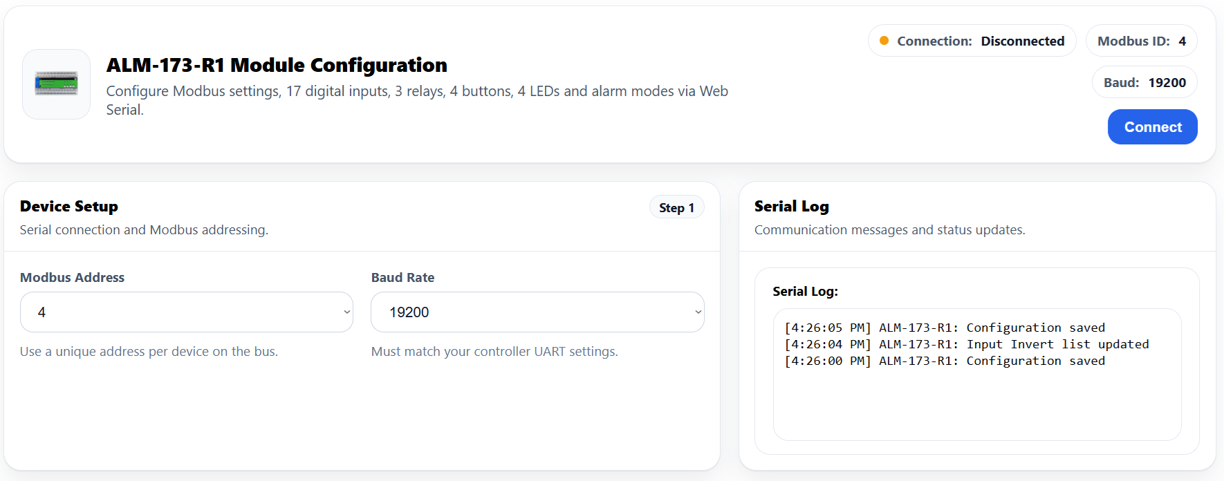
- Connect USB‑C to the module.
- Open https://www.home-master.eu/configtool-alm-173-r1 and click Connect.
- Set Modbus Address & Baud (header shows Active Modbus Configuration).
- Configure Inputs / Relays / LEDs / Buttons; changes apply live.
- Use Serial Log; Reset Device if needed (auto-reconnect).
If Connect is disabled: ensure Chromium + serial permission; on macOS/Linux verify user serial permissions and that no other app is holding the port.
5.4 Installation & Wiring
⚠️ Qualified personnel only. De-energize the panel; verify with a meter. The ALM-173-R1 is SELV—never connect mains to logic/input terminals.
5.4.1 RS‑485 Field Bus
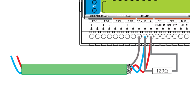
How
- Shielded twisted pair (24–22 AWG recommended).
- A→A, B→B, COM/GND→COM; keep polarity consistent.
- 120 Ω at both physical ends of the trunk.
- Single-point shield bond (usually at the controller).
- Daisy-chain topology preferred (avoid stars).
5.4.2 Primary Power (24 VDC)
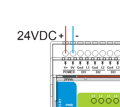
How
- Clean SELV 24 VDC to V+ / 0V.
- Observe polarity.
- Upstream fuse/breaker; proper panel bonding.
5.4.3 Digital Inputs (IN1…IN17)
How
- Wire each INx to its matching GND I.x return (dry contact / isolated low-voltage).
- Do not inject external voltage.
- Use shielded cable for long runs; avoid high‑dv/dt routes.
- Set Enable / Invert / Group in WebConfig; confirm via live dot.
4.4.4 Relays (RLY1…RLY3, COM/NO/NC)
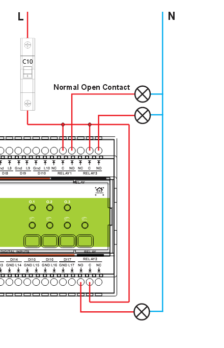
How
- External supply L → COM.
- NO (or NC if fail-active required) → load; return to N/0 V.
- Relays switch only (no internal power).
- Respect contact ratings/codes.
- Fit RC/TVS across inductive loads.
5.4.5 Final Checks
- Terminals torqued; strain relief applied.
- Isolation boundaries respected (GND_ISO vs logic).
- RS‑485 polarity/termination/biasing correct.
- Relays wired to proper COM/NO/NC; snubbers fitted.
- Power on: PWR steady; TX/RX blink under comms.
5.5 Software & UI Configuration
5.5.1 Connect
1) Plug USB‑C → 2) open the config page → 3) Connect → 4) verify Active Modbus Configuration in header → 5) use Serial Log / optional Reset Device.
5.5.2 Modbus Settings
- Address (1…255) → pick a unique RTU address.
- Baud → 9600, 19200 (default), 38400, 57600, 115200.
- Ensure the controller YAML (
uart,modbus_controller,alm_address) matches.
Changes persist in flash; you can revisit anytime.
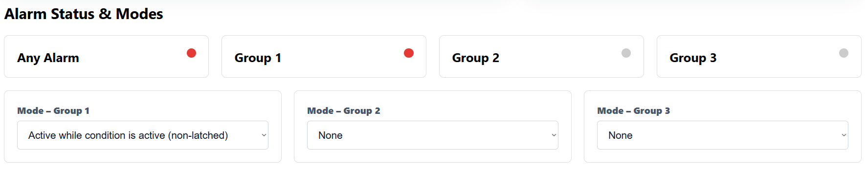
4.5.3 Alarm Modes
- None (disabled)
- Active while condition is active (momentary)
- Latched until acknowledged
Top-row indicators show live Any / G1 / G2 / G3 status.
4.5.4 Digital Inputs
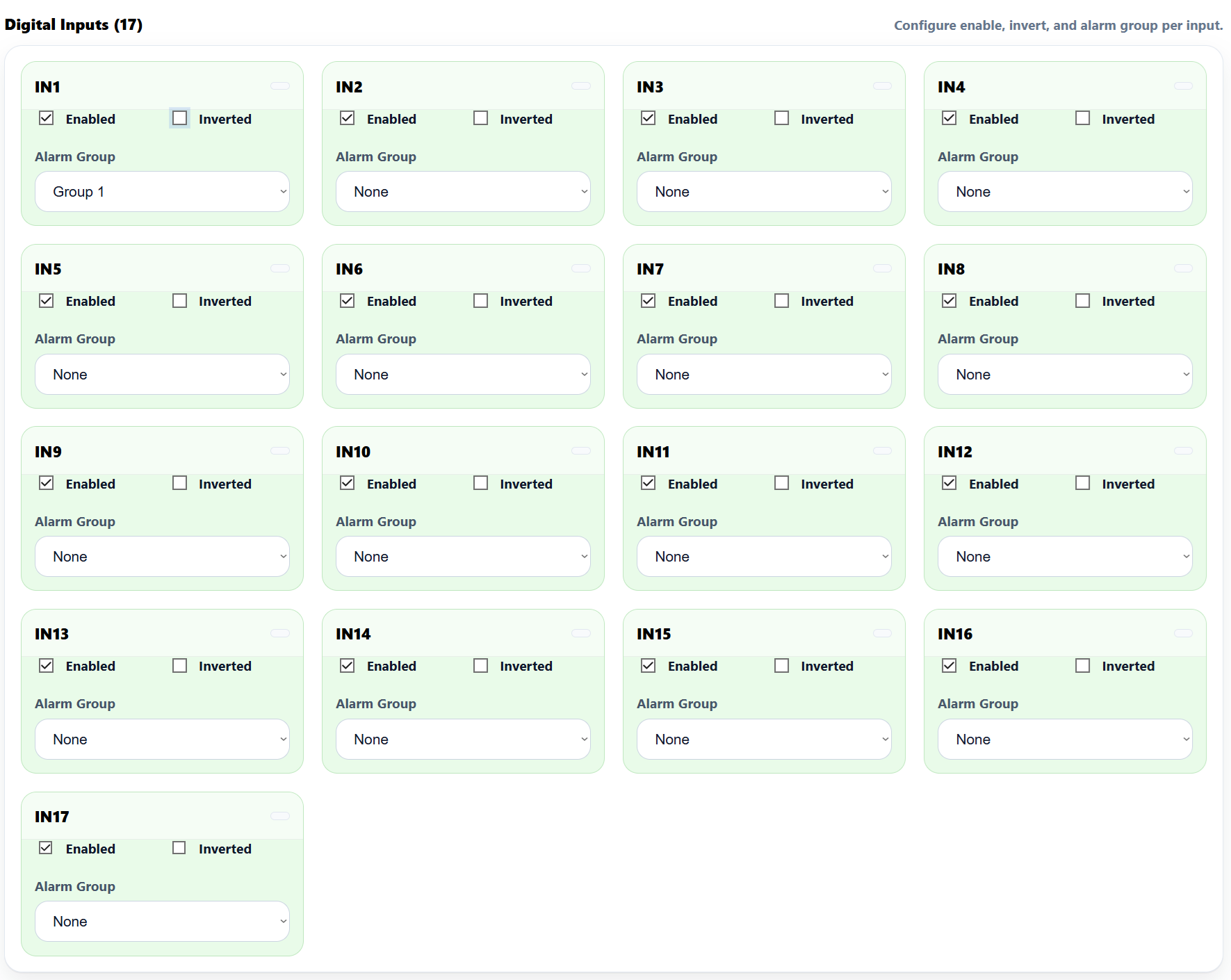
For each IN1…IN17:
- Enabled, Inverted (for NC), Alarm Group (None/1/2/3).
- Live state dot = quick wiring check.
5.5.5 Relays
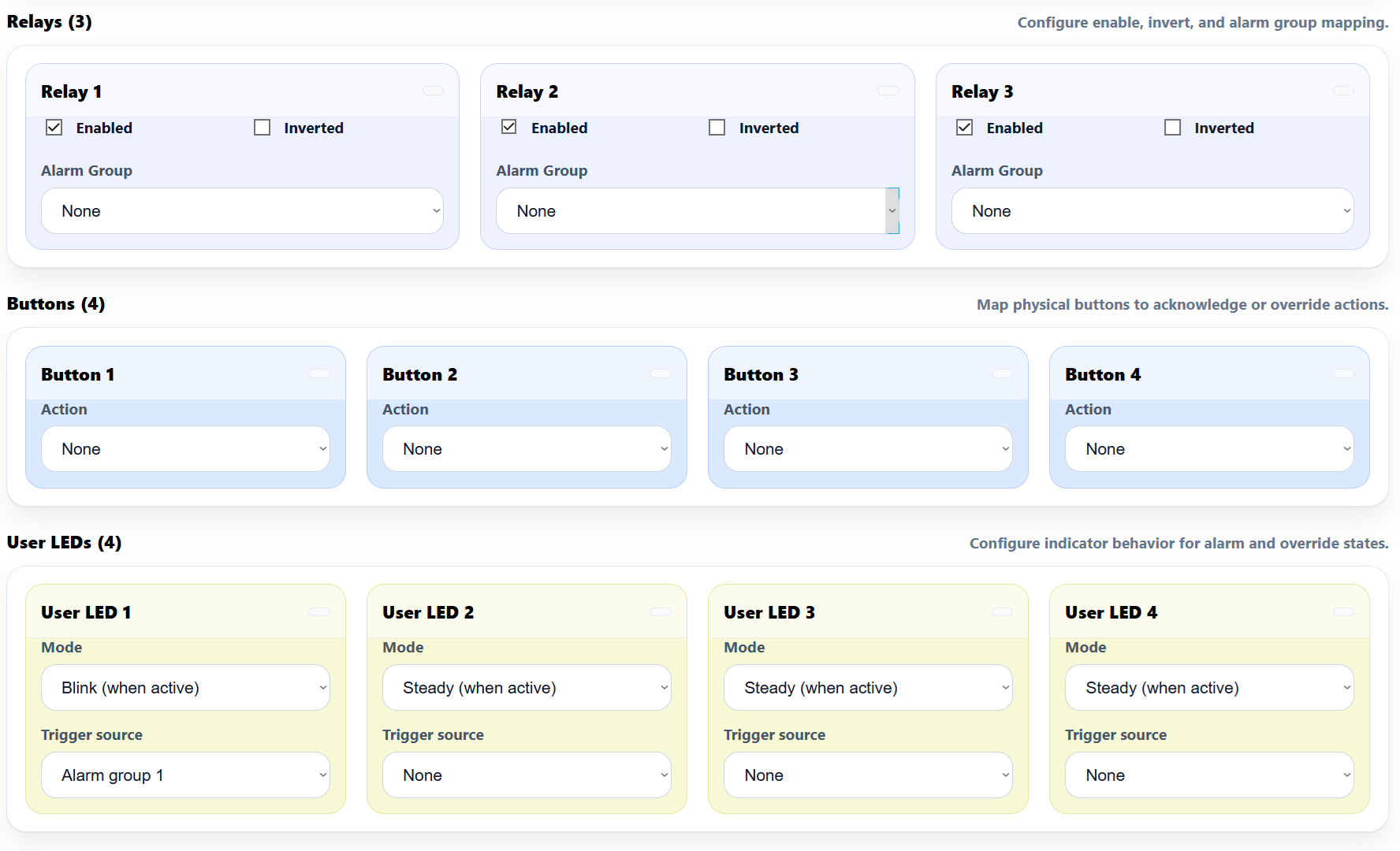
For RLY1…RLY3:
- Enabled, Inverted, Alarm Group:
- None (0) → relay ignores groups (PLC/manual only)
- Group 1/2/3 (1–3) → follows group state (incl. latching)
- Modbus/Master (4) → controller-controlled
Tip: assign a Button to “Relay x override (manual)” for quick field tests.
4.5.6 LEDs & Buttons

LEDs (1–4)
- Mode: Steady / Blink
- Source: Any / Group 1/2/3 / Relay 1–3 overridden / None
- Live state dot shows activity.
Buttons (1–4)
- Action: Ack All / Ack G1–G3 / Relay 1–3 override / None
- Live press dot indicates input.
5.6 Getting Started (3 Phases)
Phase 1 — Wire
- 24 VDC to V+ / 0V
- RS‑485 A/B/COM (terminated ends, consistent polarity)
- Inputs to IN1…IN17 with GND I.x returns
- Relays to COM/NO/NC (snub inductive loads)
- (Optional) PS/1 +12 V ISO / PS/2 +5 V ISO for sensors
Phase 2 — Configure (WebConfig)
- Set Address/Baud
- Pick Alarm modes (G1–G3)
- Map Inputs / Relays / LEDs / Buttons
- (Optional) Reset Device
See: WebConfig
Phase 3 — Integrate (Controller)
- Controller polls ALM via RS‑485
- Match Address and Baud
- Commission: read inputs & alarms; toggle relays; expose Ack/Override actions
See: Modbus RTU Communication and ESPHome Integration Guide
Verify
- LEDs: PWR ON; TX/RX blink on comms
- Inputs: toggle a few contacts; confirm live dots and Any/Gx indicators
- Relays: actuate from UI/controller; confirm field wiring (meter/indicator)
- Buttons/LEDs: test Ack/Override; confirm LED sources/modes
6. Modbus RTU Communication
Slave role: Modbus RTU over RS-485 (8N1, selectable 9600…115200 baud; typical 19200). Address: 1…255 (set via WebConfig). Data model: Discrete Inputs, Coils, Holding/Input Registers (live telemetry + configuration snapshots).
The tables below describe the factory default map used by the ALM-173-R1 firmware.
6.1 Input Registers (Read-Only)
Live, read-only snapshots convenient for dashboards and fast polling.
| Group | Address range | Type | Units (raw) | Scaling | Notes |
|---|---|---|---|---|---|
| Firmware / Device | 1100…1101 | U16×2 | enum | 1 | 1100 = firmware version, 1101 = build/variant |
| Active Modbus config | 1110…1111 | U16×2 | enum | 1 | 1110 = address (1–255), 1111 = baud code (1=9600,2=19200,3=38400,4=57600,5=115200) |
| Digital Inputs bitmap | 1120…1121 | U16×2 | bitfield | 1 | IN1…IN16 in 1120, IN17 in 1121 bit0 |
| Alarm summary | 1130 | U16 | bitfield | 1 | bit0=Any, bit1=G1, bit2=G2, bit3=G3 |
| Relay state mirrors | 1140 | U16 | bitfield | 1 | bits0..2 = RLY1..RLY3 (1=ON) |
| LED state mirrors | 1150 | U16 | bitfield | 1 | bits0..3 = LED1..LED4 (1=active) |
| Buttons pressed | 1160 | U16 | bitfield | 1 | bits0..3 = BTN1..BTN4 (1=pressed) |
All 32-bit values (if any added in future) occupy two consecutive registers (lo, hi).
6.2 Holding Registers (Read/Write)
Configuration + low-rate control values (persisted by firmware where applicable).
| Group | Address range | Type | Description |
|---|---|---|---|
| Alarm modes | 1200…1202 | U16×3 | Mode per group: 0=None, 1=Active-while, 2=Latched-until-ack (G1,G2,G3). |
| Inputs (per IN1…IN17) | 1300…1350 | U16×51 | Repeating triplet [enable, invert, group] per input. Group: 0=None, 1=G1, 2=G2, 3=G3. Layout: IN1 at 1300..1302, IN2 at 1303..1305, … IN17 at 1348..1350. |
| Relays (RLY1…RLY3) | 1400…1422 | U16×9 | Repeating triplet [enable, invert, group] per relay. Group: 0=None, 1=G1, 2=G2, 3=G3, 4=Master (controller controls). R1 at 1400..1402, R2 at 1410..1412, R3 at 1420..1422. |
| Buttons (BTN1…BTN4) | 1500…1503 | U16×4 | Action per button: 0=None, 1=Ack All, 2=Ack G1, 3=Ack G2, 4=Ack G3, 5=Relay1 override, 6=Relay2 override, 7=Relay3 override. |
| User LEDs (LED1…LED4) | 1600…1607 | U16×8 | Per LED: mode (0=Steady, 1=Blink) and source (0=None, 1=Any, 2=G1, 3=G2, 4=G3, 10=R1 overridden, 11=R2 overridden, 12=R3 overridden). |
Most daily setup is done in WebConfig; exposing these fields enables headless provisioning/backups from PLC/HA.
6.3 Discrete Inputs & Coils
Discrete Inputs (read-only flags)
| Range | Bits | Meaning |
|---|---|---|
| 00001…00017 | 17 | DI1…DI17 debounced state |
| 00050…00053 | 4 | Any Alarm, Group 1, Group 2, Group 3 |
| 00060…00062 | 3 | Relay 1…3 state mirrors |
| 00090…00093 | 4 | LED 1…4 state mirrors |
| 00100…00103 | 4 | BTN 1…4 pressed |
Coils (write – single/multiple)
| Range | Count | Action |
|---|---|---|
| 00200…00202 | 3 | Relay ON (RLY1…RLY3) |
| 00210…00212 | 3 | Relay OFF (RLY1…RLY3) |
| 00220…00222 | 3 | Override ON (force RLY1…RLY3) |
| 00230…00232 | 3 | Override OFF / Release (RLY1…RLY3) |
| 00240 | 1 | Acknowledge All (pulse) |
| 00241…00243 | 3 | Acknowledge Group 1/2/3 (pulse) |
| 00300…00316 | 17 | Enable DI i (pulse per input) |
| 00320…00336 | 17 | Disable DI i (pulse per input) |
Coils obey priority: an Override holds a relay irrespective of group/master writes until you release it.
6.4 Scaling Summary
No engineering scaling is required for ALM core points. All values are boolean/bitfield or enum codes as defined above.
6.5 Basics & Function Codes
- Physical: RS-485 half-duplex; 120 Ω termination at both ends; consistent A/B polarity; shared COM/GND recommended if separate PSUs.
- Function codes:
0x01Read Coils,0x02Read Discrete Inputs,0x03Read Holding,0x04Read Input (if utilized),0x05/0x0FWrite Coils,0x06/0x10Write Holding. - Polling: Discrete/group bits at 5–10 Hz; mirrors at 2–5 Hz; holding snapshots on change or 1–5 s.
6.6 Register Map (Summary)
Discrete Inputs
00001..00017 DI1..DI17 state
00050..00053 Any, G1, G2, G3
00060..00062 Relay1..Relay3 mirrors
00090..00093 LED1..LED4 mirrors
00100..00103 BTN1..BTN4 pressed

Coils
00200..00202 Relay ON (RLY1..RLY3)
00210..00212 Relay OFF (RLY1..RLY3)
00220..00222 Override ON (RLY1..RLY3)
00230..00232 Override OFF (RLY1..RLY3)
00240 Ack All (pulse)
00241..00243 Ack G1..G3 (pulse)
00300..00316 Enable DIi (pulse)
00320..00336 Disable DIi (pulse)

Input Registers (Read-Only)
01100 FW version (U16)
01101 FW build/variant (U16)
01110 Active address (U16)
01111 Active baud code (U16)
01120..01121 DI bitmap (U16 lo/hi)
01130 Alarm summary bitmap (Any,G1,G2,G3)
01140 Relay bitmap
01150 LED bitmap
01160 Button bitmap

Holding Registers (R/W)
01200..01202 Group modes G1..G3 (0=None,1=Active-while,2=Latched)
01300..01350 IN1..IN17 [enable,invert,group] triplets
01400..01402 RLY1 [enable,invert,group]
01410..01412 RLY2 [enable,invert,group]
01420..01422 RLY3 [enable,invert,group]
01500..01503 BTN1..BTN4 action
01600..01607 LED1..LED4 [mode,source] pairs
6.7 Override Priority
7. ESPHome Integration Guide (MicroPLC/MiniPLC + ALM-173-R1)
The HomeMaster controller (MiniPLC/MicroPLC) running ESPHome acts as the Modbus RTU master on RS‑485. It polls the ALM-173-R1 and publishes entities to Home Assistant (HA). No HA add‑ons are required—everything runs on the controller.
7.1 Architecture & Data Flow
- Topology: Home Assistant ↔ ESPHome (controller) ↔ RS‑485 ↔ ALM-173-R1
- Roles:
- ALM-173-R1: local alarm logic (inputs → groups → relays/LEDs; buttons for ack/override)
- ESPHome: Modbus I/O; exposes entities/actions to HA
- Home Assistant: dashboards, notifications, automations
Configure LED sources/modes and I/O mapping on the ALM via WebConfig; HA mainly consumes the resulting states.
7.2 Prerequisites (Power, Bus, I/O)
1) Power
- ALM: 24 VDC → V+ / 0 V
- Controller: per spec
- If supplies differ, share COM/GND between devices
2) RS‑485
- A↔A, B↔B (twisted pair), COM shared
- Terminate two physical ends (~120 Ω), bias at master
- Default serial: 19200 8N1; set address in WebConfig (examples use
5)
3) Field I/O (typical)
- IN1…IN17: dry contacts → map to Group 1/2/3
- RLY1…RLY3: siren/lock/indicator (dry contacts)
- Buttons/LEDs: local ack/override & status
7.3 ESPHome Minimal Config (Enable Modbus + Import ALM Package)
Use these exact variable names: alm_prefix, alm_id, alm_address.
uart:
  id: uart_modbus
  tx_pin: 17
  rx_pin: 16
  baud_rate: 19200
  parity: NONE
  stop_bits: 1

modbus:
  id: modbus_bus
  uart_id: uart_modbus

packages:
  alm1:
    url: https://github.com/isystemsautomation/homemaster-dev
    ref: main
    files:
      - path: ALM-173-R1/Firmware/default_alm_173_r1_plc/default_alm_173_r1_plc.yaml
        vars:
          alm_prefix: "ALM#1"   # shown in HA entity names
          alm_id: alm_1         # unique internal ID
          alm_address: 5        # ALM Modbus ID from WebConfig
    refresh: 1d
For multiple ALMs, duplicate the
alm1:block (alm2:,alm3:…) with uniquealm_id/alm_prefix/alm_address.
7.4 Entities Exposed by the Package
- Binary sensors
- IN1…IN17 (debounced)
- Any Alarm, Group 1, Group 2, Group 3
- Buttons pressed (BTN1…BTN4, optional diagnostics)
- Relay/LED mirrors (dashboard readback)
- Switches
- RLY1…RLY3 (manual/HA actuation)
- Acknowledge (All / G1 / G2 / G3)
- Override (force R1/R2/R3 ON/OFF, then release)
- Numbers/Selects (optional)
- Readbacks for address/baud, group modes, and per‑channel enable/invert/group (for diagnostics/provisioning)
7.5 Command Helpers (Writes)
Package includes pulse‑safe helpers (auto‑release):
- Relays: R1/R2/R3 ON / OFF
- Overrides: Override ON/OFF for R1/R2/R3 (forces relay regardless of group until released)
- Acknowledges: Ack All, Ack G1, Ack G2, Ack G3
- (Optional) Inputs: Enable/Disable INx commissioning pulses
These appear as ESPHome switches/scripts usable in HA automations.
7.6 Using Your MiniPLC YAML with ALM
- Keep your existing
uart:andmodbus:blocks. - Add the
packages:block (above) and setalm_addressto the device address in WebConfig. - Flash the controller. ESPHome discovers entities under
alm_prefix(e.g.,ALM#1 IN1,ALM#1 Relay 1). - Build dashboards and add buttons for Ack / Override actions as needed.
7.7 Home Assistant Setup & Automations
1) Add device: Settings → Devices & Services → ESPHome → add by hostname/IP.
2) Dashboards
- Annunciator: tiles for Any/G1/G2/G3, plus Ack All button
- Zones: IN1…IN17 grouped by area; toggles for RLY1/2/3
- Service/Night Mode: helper booleans that gate siren/override logic
3) Automations (examples)
- Any Alarm → ON: push notification + optional light flash; if
service_mode = offthen energize Relay 1 (siren) - Group X (latched) → ON: prompt Ack Group X
- Modbus unavailable: critical alert + persistent HA notification
7.8 Troubleshooting
- No data/timeouts: check A/B polarity, COM/GND reference (if separate PSUs), termination/bias.
- Wrong package vars: must use
alm_prefix,alm_id,alm_address(exact names). - Relays not responding: ensure Enabled in WebConfig and not overridden.
- Latched alarms won’t clear: input must be normal and an appropriate Ack must be sent.
- Multiple ALMs: each needs a unique Modbus address and alm_prefix.
7.9 Version & Compatibility
- Tested with ESPHome 2025.8.0
- Controller YAML typically uses ESP‑IDF; Arduino works if preferred (adjust platform)
8. Programming & Customization
8.1 Supported Languages
- MicroPython
- C/C++
- Arduino IDE
8.2 Flashing via USB-C
- Connect USB‑C.
- Enter boot/flash mode if required.
- Upload the provided firmware/source.
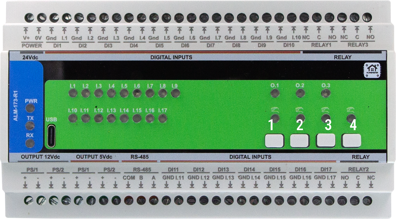
Boot/Reset combinations:
- Buttons 1 + 2 → forces the module into BOOT mode.
- Buttons 3 + 4 → triggers a hardware RESET. These behaviors are handled in hardware. Use these combinations during firmware flashing or to restart the device manually.
📷 Button numbering reference:
8.4 Firmware Updates
To update the firmware, use the Arduino IDE or PlatformIO via USB-C:
- Connect the USB‑C cable to the module.
- Press Buttons 1 + 2 together to enter BOOT mode.
- Upload the updated binary located in
Firmware/default_alm_173_r1/.
⚠️ Configuration stored in EEPROM is preserved during firmware updates unless manually cleared.
8.3 Arduino
- Select the appropriate board profile (Generic RP2350).
- In the Tools select Flash size 2MB (Sketch: 1MB, FS: 1MB )
-
Add
- #include
- #include
- #include
- #include
- #include
- #include
- #include
- #include
- #include “hardware/watchdog.h”
9. Maintenance & Troubleshooting
(Section placeholder for future additions.)
10. Open Source & Licensing
Licensing
This project uses a hybrid licensing model.
Hardware
Hardware designs (schematics, PCB layouts, BOMs) are licensed under: CERN-OHL-W v2
Firmware & ESPHome Integration
All firmware, ESPHome configurations, and software components are licensed under: MIT License
This ensures full compatibility with ESPHome and Home Assistant while protecting hardware designs.
See LICENSE files in each directory for full terms.
11. Downloads
The following key project resources are included in this repository:
-
🧠 Firmware (Arduino/PlatformIO):
Firmware/default_alm_173_r1/Main sketch implementing relays, button overrides, alarms, Modbus RTU, and WebSerial support. -
🛠 Web Config Tool:
Firmware/ConfigToolPage.htmlHTML‑based USB Web Serial configuration UI, used for meter options, calibration, relays, alarms, etc. -
📷 Images & Visual Documentation:
Images/Contains UI screenshots, module photos, diagrams, and layout references used in this documentation. -
📐 Hardware Schematics:
Schematics/Includes Field Board and MCU Board schematics in PDF format for hardware developers and integrators. -
📖 Datasheet & Documentation (if available):
Manuals/Contains PDF datasheets or technical overviews, if applicable.
12. Support
If you need help using or configuring the ALM-173-R1 module, the following resources are available:
- 🛠 Web Config Tool – Configure and calibrate via USB‑C in your browser.
- 🌐 Official Support Page – Knowledge base and contact options.
📡 Community & Updates
- Hackster Projects – Integration guides, wiring, and code examples.
- YouTube Channel – Video tutorials and module demos.
- Reddit Community – Questions, help, and user contributions.
- Instagram – Visual updates and product insights.